
Related Manuals for Mean Well CMU2C


Summary of Contents for Mean Well CMU2C
- Page 1 C M U 2 C I n sta l l at i o n m a n u a l Multi-Industry General Purpose Smart Controller Pragramable Intelligent Smart UI...
- Page 2 CMU2C is a fully digitalized smart controller that can execute tasks of monitoring and controlling over power system. It can be accessed t h ro u g h l o c a l / re m o t e a n d w i re d c o n n e c t i o n . W i t h f o u r b u i l t- i n configurable relay contacts, users can flexibly monitor specific events or alarms and take suitable action accordingly.
- Page 3 Index 1.Safety Guidelines 6.Maintenance 1 1 . Passwords 6.1 Firmware update instruction 2.Introduction odel Encoding 7.Warranty 2.2 Features 2 3 pecification echanical Specification 3.Installation & Wiring Installation .2 C onfiguration .3 S D Card Installation 4 User Interface 4.1 Panel Description 4 2 ED indication .
-
Page 4: 1.Safety Guidelines
System in Setting page. Selectable PMBus and CAN bus communication protocols By default, the password is “ CMU2C ”. Support Data/ Event log with date and time Support max. 32G SDHC SD card Support firmware upgrade Four user programmable relay outputs for conventional remote... -
Page 5: Specification
6.The RTC power supply used super capacitors, which can last for only 7 days. If the time exceeds the limit, the RTC date must be re-adjusted. 7.Up to 40 power supplies can be operate in parallel connection, and possible up to 48 power supplies. and optional CMU2A-#R# available 8.Order model only CMU2C-P##, CMU2C-R-P##, CMU2C-C##, CMU2C-R-C## 22.5 ※... -
Page 6: Extension Cards
※ PMBus(C card) Rack-mount typ Unit:mm 483.6 466.2 HOT KEY JK601 JK600 Enter ※ RS-232/RS485/USB(R card) 81.1 JK22 JK52 JK51 JK53 TB51 Slot 3 Slot 2 Slot 1 (Ethernet) (CANBus) (PMBus) (RS-232) (RS-485) TB80 (RS-485) CN38 CN39 CN36 CN37 JK880 (DOUT) (DIN) (AIN) -
Page 7: Installation And Wiring
3.Installation & Wiring Desktop 3 Installation .1. Standalone Type 3.1.1.1 Wall Mounting M3*6mm Plastic wall plug (M4*20mm) M4*25mm .1. Rack-mount type 3.1.1.2 Accessory Installation Din Rail M5*12mm M3*6mm... - Page 8 3.3 SD ard nstallation 3.2 Configuration CMU2 supports SDHC type SD cards with capacity of 4G - 32G The CMU2 is able to recognize up to three communication ports for PMBus or CAN bus device addressing, each port recognized as an Standalone ype i n d e p e n d e n t g r o u p .
- Page 9 After the top cover is removed, please follow the steps below to insert a SD card. After a SD card is inserted , please reinstall the cover. Lock the slot cover Rack-mount type Please use a Phillips screwdriver to remove Unlock the slot cover the protective cover.
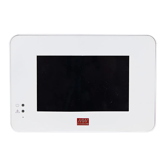
- Page 10 4.User Interface 4.1 Panel Description Power indicator: Used to display whether the CMU is powered on. Alarm indicator: Used to display operation status of CMU2. Touch panel: Tap to select function al pages Open the slot cover and insert the SD card Hotkey buttons ress...
- Page 11 Pin ssignment of CN38 CN38 DOUT 5 DOUT 4 DOUT 3 DOUT 2 DOUT 1 HOT KEY Pin No. Function Description The isolated digital output signal with FG as reference Open collector signal, Max. singal voltage is 5V with FG DOUT 1 Enter as reference...
- Page 12 Pin ssignment of CN39 Pin ssignment of TB1 CN39 AC/N AC/L DIN 5 DIN 4 DIN 3 DIN 2 DIN 1 Pin No. Function Description Pin No. Function Description AC/N AC input neutral wire The isolated digital input signal with FG as reference Open collector signal AC/L AC input live wire...
- Page 13 Pin ssignment of TB30 Pin ssignment of JK51 JK51 TB30 Relay4 Relay4 Relay4 Relay3 Relay3 Relay3 Relay2 Relay2 Relay2 Relay1 Relay1 Relay1 CONTROL -COM -COM -COM -COM Pin No. Function Description Pin No. Function Description Relay1-NO Normal-open contact of programmable relay1 1,2,3,5,9, Not use 10,11,13...
- Page 14 Pin ssignment of JK52 Pin ssignment of JK22 JK52 JK22 CONTROL CAN-H CAN-L Pin No. Function Description Pin No. Function Description Transmit data used in the Ethernet interface 1,2,3,5,9, Not use 10,11,13 Transmit data used in the Ethernet interface 4 12 CONTROL Remote ON/OFF control pin (Note) Receive data used in the Ethernet interface...
-
Page 15: Operation
5.Operation Home page – options The following functions are available in the home page: The CMU2 communicates with rack powers via PMBus and CANBus Name Description interfaces to achieve operation monitoring and remote control functions of system power. In addition, CMU2 supports communication Users can enter other function pages by taping interfaces of touch panel and network. - Page 16 5.1.2 Status Name Description Status page displays operation status of PSU, I/O signal and Relays. 1) Th s e e information boxes are used to display online 5. . . PSU 1 2 1 and operation status of the PSUs. There are four page displays status of PSUs connected.
- Page 17 5.1.2.2 I/O signal 5.1.2.3 Relay I/O signal page displays digital status of inputs and outputs. The relay page is used to display output state and setting There 5 channels each. parameters of the four programmable relays. I/O signal page - options The following functions are available in the I/O signal page Relay...
- Page 18 5.1.3 Setting 5.1.3.2 Output adj The Setting page can do settings of PSU on/off, Output adj, I/O The output adj page provides functions to set output voltage signal, Rely and System. and current. It also displays maximum and minimum adjustable Detailed information about the functions, please refer to following values for user convenience.
- Page 19 5.1.3.3 I/O signal Trigger definitions: I/O signal page is used to set five digital output channels to (1) Alarm: trigger the output channel when one of the supplies realize alarm functions you need. meets alarm conditions, such as OVP, OLP, short circuit or any In addition, the channels also can work with digital inputs to do of the protections (default).
- Page 20 1Sec、5Sec、10Sec、 Fan Lock Password is required to enter the menu, the default password is 30Sec、1~10Min On, Off “ CMU2C ” High, Low DI CH1 - DI CH5 5.1.3. . Network The COMMON is connected to the NO (Normally Open) when...
- Page 21 (4)Email sends when there is any new event log that occurs. Email sample: Sender Sent: Tuesday, August 03, 2021 18:07 PM From: XXXX@meanwell.com Subject Subject: CMU2C Event Log(2021/08/03 18:07) Recipient To: XXXX Abnormal conditions 5.1.3. . Security ou can change...
- Page 22 Screen page – options Log Config. page – options The following functions are available in screen page The following functions are available in Log Config. page Name Description Name Description Tap the box to select a certain time to turn off Tap the box to select a certain interval to the screen.
- Page 23 Misc. page options – Name Description The following functions are available in Log Misc. page: This function is used to delete the saved event Name Description log permanently. Tapping the boxes can change the date and 〝 Execute 〞 then 〝...
- Page 24 Name Description Name Description 1)Choose whether to synchronize the clock It displays the SD card capacity and usage with an internet time. information. Synchronization with nternet Tap 〝 xecute 〞 then 〝 〞to format the SD SD card card. formatting 2)There are 25 options for time zone selection, UTC-12 - UTC+12.
- Page 25 5.1.4.1 ata log Name Description Data Log stores the measurement data at selected intervals and 「<」「>」can be used to select operation Data provides a full history database for users to extract and load. information that wants to view, including bus selection One page can display 8 data and there are 180 pages in total in voltage, current in total or in single.
- Page 26 5.2 Web-based User Interface Event Log page – options The following functions are available in Event Log page: 5.2.1 System requirements ◎System requirements Name Description 1.Windows 10 1)「^」「v」can be used to select pages, single 2.AMD or Intel Pentium 133MHz or better based computer tap to display the next or previous pages.
- Page 27 Only connect the PC to the CMU2 and make sure there is no other devices connected to the PC. Click the "Network and Internet Connections" option. Then click the "Local Area Connection". Select "Internet Protocol (TCP/IP)", and then click the "Properties" button. If there are "Internet Protocol Version 4 (TCP/IPv4)"...
- Page 28 If the table shows below, it means that your RJ-45 cable is not 5.2. H connected properly or the IP address you set is incorrect. HOME page of the built-in web displays output power, number of PSU connected, bus votage, total current, information on firmware versions.
- Page 29 5.2.5.2 Digital/Relay This page displays status of the digital input/ output and relays. Digital Input/ Output Digital Input: There are 2 conditions, it displays green when logic high whereas it displays gray when logic low. It remains logic high when no signal connected due to hardware design.
- Page 30 After setting, click to write your new parameters. Please APPLY refer to the table below for detailed triggering functions. SOURCE TRIGGER ACTIVE DELAY Any (default), : You cannot turn on/off PSUs no onlie. OVP, OLP, Short, Alarm (default) OTP, AC-Fail, High (default), Immed.(default)、...
- Page 31 Active: Source: Determine the logic level when outputting. High (high level): Alarm, PSU or digital input channels are available to be 5V; Low (low level): 0V. selected. After selection, the corresponding trigger conditions will appear. For instance: trigger definitions will Delay: move to relevant protection options for the rack powers when Determine how long to delay before outputting when the...
- Page 32 : FireFox does not support a date picker function, users has to enter date manually. Data Log information 5.2.8 SYSTEM YSTEM page provides setting of Network, Notice, Security and Data/Event Log. 5.2.8.1 Network 5.2.7.2 vent og Network page provides IP address setting. The new settings Event Log stores information about all abnormal events that will take effect after power recycling.
- Page 33 Email sample: Sender Sent: Tuesday, August 03, 2021 18:07 PM From: XXXX@meanwell.com Subject Subject: CMU2C Event Log(2021/08/03 18:07) Recipient To: XXXX Abnormal conditions 5.2.8.3 Security 5.2.8.2 Notice You can change your password in this page , with max 15 words.
- Page 34 The device supports Modbus TCP communication protocol. Clients Click the box to select a certain interval to record operation are able to read and write parameters of the CMU2C (server) through data of the rack powers. the protocol, including remote ON/OFF, output voltage/current...
- Page 35 5.3.3 MBAP Header Definition FC = 03 MBAP Header consists of the following parts: Request: Starting Address Quantity of Registers Fields Length Description 2 Bytes 2 Bytes Transaction Identifier 2 bytes Identification of a MODBUS Request / Response transaction. Response: Initialized by the client and recopied by the server from the Byte Count...
- Page 36 FC = 10 Register Command Supported # of data Description Addresses Function Codes Name Bytes Request: Set output voltage of 0x0010 VOUT_SET 0x03、0x06、 Starting Address Quantity of Registers Byte Count Registers Value the all PSUs (All) 0x10 2 Bytes 2 Bytes 1 Byte N* x 2 Bytes (format: value, F=0.1)
- Page 37 Status Reading of PSU (PSU#0 - 47) (address range:0x0200~ Status Reading of Event Log (address range:0x6000~0x07F3F): 0x0229): Command # of data Register Supported Description Register Command Supported # of data Addresses Name Function Codes Bytes Description Addresses Function Codes Name Bytes Read Event log #1 0x6000...
- Page 38 Low byte: High byte: Bit 0 - 3 Delay Bit 0 - 3 Trigger Please refer to the table below for detailed parameter setting. Please refer to the table below for detailed parameter setting. Bit 4 -7 Trigger Bit 4 - 7 Source Please refer to the table below for detailed parameter setting.
- Page 39 Digital I/O Status (0x0101) Definition: Bit 3 OLP:Over-load protection Bit7 Bit6 Bit5 Bit4 Bit3 Bit2 Bit1 Bit0 0=DC current normal High byte 1=DC over current protected Low byte Bit 4 SHORT:Short-circuit protection Low byte: 0=Shorted circuit do not exist Bit 0 D01:...
- Page 40 MFR_REVISION_B0B5 (0x021C+0x30*N ~0x021E+0x30*N) is the firmware Device Event Date Time revision (hexadecimal). A range of 0x00 (R00.0) ~ 0xFE (R25.4) represents (Max 10 Bytes) (Max 20 Bytes) (Max 10 Bytes) (Max 8 Bytes) the firmware version of a MCU; 0xFF represents on MCU existed System 1、EEPROM Error 20YY/MM/DD...
- Page 41 Response: Request: 0x00020000000901 0x03 0x06 0x0A0A0AFFFFFF 0x00020000000601 0x06 0x0000 0x0001 0x00020000000901: MBAP Header 0x00020000000601: MBAP Header 0x03: Function code 3 ( ead Analog Output Holding Registers) 0x06: Function code 6 (Preset Single Register) 0x06: The number of data bytes to follow (6 bytes) 0x0000: The Data Address of the register 0x0A 0A 0A FF FF FF: means that the firmware version of the 0x0001: The value to write...
- Page 42 0x0001: The total number of registers requested ( ead only 1 Click the red mark to add latest firmware files. registers from 0x6000) Response: Read Array Log is a self-definition of Mean Well, response data frame is as the following Choose Files 5 files UPLOAD...
-
Page 43: Warranty
CMU2. the warranty effectively. ※ MEAN WELL possesses the right to adjust the content of this manual. Pleaserefertothelatest version ofourmanual on ourwebsite. https://www.meanwell.com MEAN WELL WEB... - Page 44 N o . 2 8 , W u q u a n 3 r d R d . , W u g u D i s t . , N e w Ta i p e i C i t y 2 4 8 , Ta i w a n...
Need help?
Do you have a question about the CMU2C and is the answer not in the manual?
Questions and answers