Table of Contents
Advertisement
Quick Links
© Copyright 2020
EVERTZ MICROSYSTEMS LTD.
5292 John Lucas Drive
Burlington, Ontario
Canada L7L 5Z9
Phone:
+1 905-335-3700
Sales:
sales@evertz.com
Tech Support: service@evertz.com
Web Page:
http://www.evertz.com
Version 1.0, January 2020
The material contained in this manual consists of information that is the property of Evertz Microsystems and is intended solely for the use of
purchasers of the 2406DT13 Series product. Evertz Microsystems expressly prohibits the use of this manual for any purpose other than the
operation of the 2406DT13 Series product. Due to on going research and development, features and specifications in this manual are subject to
change without notice.
All rights reserved. No part of this publication may be reproduced without the express written permission of Evertz Microsystems Ltd. Copies of
this manual can be ordered from your Evertz dealer or from Evertz Microsystems.
2406DT13-F2
User Manual
Fax: +1 905-335-3573
Fax: +1 905-335-7571
Twitter:
@EvertzTV
Advertisement
Table of Contents

Subscribe to Our Youtube Channel
Related Manuals for evertz 2406DT13-F2


Summary of Contents for evertz 2406DT13-F2
- Page 1 Version 1.0, January 2020 The material contained in this manual consists of information that is the property of Evertz Microsystems and is intended solely for the use of purchasers of the 2406DT13 Series product. Evertz Microsystems expressly prohibits the use of this manual for any purpose other than the operation of the 2406DT13 Series product.
- Page 2 This page left intentionally blank...
- Page 3 IMPORTANT SAFETY INSTRUCTIONS The lightning flash with arrowhead symbol within an equilateral triangle is intended to alert the user to the presence of uninsulated “Dangerous voltage” within the product’s enclosure that may be of sufficient magnitude to constitute a risk of electric shock to persons. The exclamation point within an equilateral triangle is intended to alert the user to the presence of important operating and maintenance (Servicing) instructions in the literature accompanying the product.
- Page 4 WARNING Changes or Modifications not expressly approved by Evertz Microsystems Ltd. could void the user’s authority to operate the equipment. Use of unshielded plugs or cables may cause radiation interference. Properly shielded interface cables...
-
Page 5: Table Of Contents
2406DT13-F2 User Manual TABLE OF CONTENTS OVERVIEW ........................... 1 SPECIFICATIONS ......................... 5 OPERATION ..........................7 3.1. CONNECTIONS ........................7 3.2. INSTALLATION ........................7 3.3. LED INDICATIONS ....................... 8 3.4. TROUBLE SHOOTING ......................8 Page - i Revision 1.0... - Page 6 2406DT13-F2 User Manual FIGURES Figure 1-1 : 2406DT13-F2 Front View ......................1 Figure 1-2 : 2406DT13-F2 Rear View ......................2 Figure 1-3 : 2406DT13-F2 Block Diagram ....................... 3 Figure 3-1 : 2406DT13-F2 Connection Diagram ....................7 Figure 3-2 : DIN-RAIL Mounting ........................7 Figure 3-3 : Wall/Panel Mounting ........................
- Page 7 January 2020 Information contained in this manual is believed to be accurate and reliable. However, Evertz assumes no responsibility for the use thereof nor for the rights of third parties, which may be affected in any way by the use thereof. Any representations in this document concerning performance of Evertz products are for informational use only and are not warranties of future performance, either expressed or implied.
- Page 8 2406DT13-F2 User Manual This page left intentionally blank Page - iv Revision 1.0...
-
Page 9: Overview
RS-232, RS-422 or RS-485 data over a pair of single mode fibers. Used as a pair, the maximum end to end single mode fiber distance is 40km. The 2406DT13-F2 supports data rates up to 115.2kbps and is capable of auto sensing the applied data format. -
Page 10: Figure 1-2 : 2406Dt13-F2 Rear View
2406DT13-F2 User Manual Figure 1-2 : 2406DT13-F2 Rear View Features & Benefits • Point to point fiber links • Industrial grade enclosed in a rugged and rustless ABS housing • LED status indications • Transmits serial data (RS-232, RS-422 or RS-485) over long distances through fiber cables (Single-mode: 25 miles or 40km) •... -
Page 11: Figure 1-3 : 2406Dt13-F2 Block Diagram
2406DT13-F2 User Manual Figure 1-3 : 2406DT13-F2 Block Diagram Note: Supports one data type at any given time. Page - 3 Revision 1.0... - Page 12 2406DT13-F2 User Manual This page left intentionally blank Page - 4 Revision 1.0...
-
Page 13: Specifications
2406DT13-F2 User Manual SPECIFICATIONS Compatibility EIA/TIA RS-232C, RS-485 and RS-422 standard Number of signals Power Source 9 to 30VDC (External AC to DC power adapter included) External AC/DC Power Adapter 9VDC/500mA (Input: 100~240VAC 50/60Hz, US type A plug) Current Consumption... - Page 14 2406DT13-F2 User Manual This page left intentionally blank Page - 6 Revision 1.0...
-
Page 15: Operation
UP to 128 NODES UP to 128 NODES Single-Mode: 25 Miles (40KM) Multi-Mode: 3 Miles (5KM) RS-232 RS-232 Figure 3-1 : 2406DT13-F2 Connection Diagram Note: Connect one data type at a time. 3.2. INSTALLATION Figure 3-2 : DIN-RAIL Mounting Page - 7... -
Page 16: Led Indications
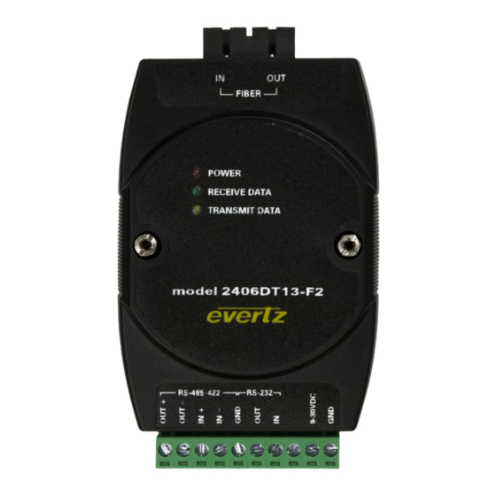
2406DT13-F2 User Manual Figure 3-3 : Wall/Panel Mounting 3.3. LED INDICATIONS The Three LEDs indicate as follows: POWER: Power indicator. Steady: Power On. OFF: Power Off. RECEIVE DATA: RX Indicator. Flashing: Receiving data from Fiber links. TRANSMIT DATA: TX Indicator.
Need help?
Do you have a question about the 2406DT13-F2 and is the answer not in the manual?
Questions and answers