Table of Contents
Advertisement
Quick Links
AUGUST 2001
IC141C-R2
IC189C
4-Port Serial Host Adapter PCI
CUSTOMER
Order toll-free in the U.S. 24 hours, 7 A.M. Monday to midnight Friday: 877-877-BBOX
FREE technical support, 24 hours a day, 7 days a week: Call 724-746-5500 or fax 724-746-0746
SUPPORT
Mail order: Black Box Corporation, 1000 Park Drive, Lawrence, PA 15055-1018
INFORMATION
Web site: www.blackbox.com • E-mail: info@blackbox.com
Advertisement
Table of Contents

Subscribe to Our Youtube Channel
Related Manuals for Black Box IC189C


Summary of Contents for Black Box IC189C
- Page 1 Order toll-free in the U.S. 24 hours, 7 A.M. Monday to midnight Friday: 877-877-BBOX FREE technical support, 24 hours a day, 7 days a week: Call 724-746-5500 or fax 724-746-0746 SUPPORT Mail order: Black Box Corporation, 1000 Park Drive, Lawrence, PA 15055-1018 INFORMATION Web site: www.blackbox.com • E-mail: info@blackbox.com...
- Page 2 4-PORT SERIAL HOST ADAPTER PCI FEDERAL COMMUNICATIONS COMMISSION AND INDUSTRY CANADA RADIO-FREQUENCY INTERFERENCE STATEMENTS This equipment generates, uses, and can radiate radio-frequency energy and if not installed and used properly, that is, in strict accordance with the manufacturer’s instructions, may cause interference to radio communication. It has been tested and found to comply with the limits for a Class A computing device in accordance with the specifications in Subpart J of Part 15 of FCC rules, which are designed to provide reasonable protection against such interference when the equipment is...
- Page 3 4-PORT SERIAL HOST ADAPTER PCI NORMAS OFICIALES MEXICANAS (NOM) ELECTRICAL SAFETY STATEMENT INSTRUCCIONES DE SEGURIDAD 1. Todas las instrucciones de seguridad y operación deberán ser leídas antes de que el aparato eléctrico sea operado. 2. Las instrucciones de seguridad y operación deberán ser guardadas para referencia futura.
- Page 4 4-PORT SERIAL HOST ADAPTER PCI 12. Precaución debe ser tomada de tal manera que la tierra fisica y la polarización del equipo no sea eliminada. 13. Los cables de la fuente de poder deben ser guiados de tal manera que no sean pisados ni pellizcados por objetos colocados sobre o contra ellos, poniendo particular atención a los contactos y receptáculos donde salen del aparato.
- Page 5 4-PORT SERIAL HOST ADAPTER PCI TRADEMARKS USED IN THIS MANUAL OS/2 is a registered trademark of International Business Machines Corporation. Windows and Windows NT are registered trademarks of Microsoft Corporation. Any other trademarks mentioned in this manual are acknowledged to be the property of the trademark owners.
-
Page 6: Table Of Contents
4-PORT SERIAL HOST ADAPTER PCI Contents Chapter Page 1. Specifications ............6 2. -
Page 7: Specifications
4-PORT SERIAL HOST ADAPTER PCI 1. Specifications Communications Chip—IC141C-R2: 16550 UART (you can remove this UART and install a 16850 or 16950 UART for better performance); IC189C: 16850 UART Maximum Distance—5000 ft. (1524 m) Operation—RS-422/485 Protocol—Asynchronous Speed—460.8 kbps CE Approval—Yes Connectors—(1) DB37 male on card, (1) DB37 female and (4) DB9 male on... -
Page 8: Introduction
16850 or 16950 UART in its place. The 128-byte FIFO you get with the 16850 or 16950 UART allows the card to deliver better performance than with the 16550 UART. The IC189C Adapter already has the 16850 UART installed. RS-422 provides excellent communications for long-distance device connections up to 4000 ft. -
Page 9: Factory-Default Settings
4-PORT SERIAL HOST ADAPTER PCI 2.3 Factory-Default Settings The factory-default settings are described in Table 2-1. Table 2-1. Factory-Default Settings. Port # Clock DIV Mode Enable Mode Port 1 Auto Port 2 Auto Port 3 Auto Port 4 Auto To install the 4-Port Serial Host Adapter PCI using factory-default settings, skip Chapter 3 and go on to Chapter 4. -
Page 10: Card Setup
4-PORT SERIAL HOST ADAPTER PCI 3. Card Setup NOTE In all cases J1x is for port 1, J2x for port 2, J3x for port 3, and J4x for port 4. 3.1 RS-485 Enable Modes RS-485 is ideal for multi-drop or network environments. It requires a tri-state driver that will allow the electrical presence of the driver to be removed from the line. -
Page 11: Interface Mode Examples J1B -J4B
4-PORT SERIAL HOST ADAPTER PCI 3.2 Interface Mode Examples J1B – J4B Figure 3-1. Headers J1B – J4B, RS-422. Figure 3-2. Headers J1B – J4B, RS-485 “Auto” Enabled, with “No Echo.” Figure 3-3. Headers J1B – J4B, RS-485 “Auto” Enabled, with “Echo.”... -
Page 12: Address And Irq Selection
4-PORT SERIAL HOST ADAPTER PCI Figure 3-4. Headers J1B – J4B, RS-485 “RTS” Enabled, with “No Echo.” Figure 3-5. Headers J1B – J4B, RS-485 “RTS” Enabled, with “Echo.” 3.3 Address and IRQ Selection The 4-Port Serial Host Adapter PCI is automatically assigned I/O addresses and IRQs by your motherboard BIOS. -
Page 13: Clock Modes
4-PORT SERIAL HOST ADAPTER PCI Table 3-1. Line Termination Jumper Position Functions. Name Function Adds or removes the 1K-ohm pull-down resistor in the RS-422/RS-485 receiver circuit (Receive data only). Adds or removes the 1K-ohm pull-up resistor in the RS-422/RS-485 receiver circuit (Receive data only). Adds or removes the 120-ohm termination. - Page 14 4-PORT SERIAL HOST ADAPTER PCI Figure 3-7. Clocking Mode “Divide By 4.” To double these rates up to a maximum rate of 230.4 kbps, place the jumper in the divide-by-2 (marked DIV2) position. Figure 3-8. Clocking Mode “Divide By 2.”...
-
Page 15: Baud Rates And Divisors For The "Div1" Mode
4-PORT SERIAL HOST ADAPTER PCI 3.5.1 B “DIV1” M ATES AND IVISORS FOR THE Table 3-2 shows some common data rates and the rates you should choose to match them if using the adapter in the “DIV1” mode. Table 3-2. Baud Rates for the “DIV1” Mode. For This Data Rate Choose This Data Rate 1200 bps... - Page 16 4-PORT SERIAL HOST ADAPTER PCI If your communications package allows the use of baud-rate divisors, choose the appropriate divisor from Table 3-3. Table 3-3. Baud-Rate Divisors for the “DIV1” Mode. For This Data Rate Choose This Divisor 1200 bps 2400 bps 4800 bps 9600 bps 19.2 kbps...
-
Page 17: Baud Rates And Divisors For The "Div2" Mode
4-PORT SERIAL HOST ADAPTER PCI 3.5.2 B “DIV2” M ATES AND IVISORS FOR THE Table 3-43 shows some common data rates and the rates you should choose to match them if using the adapter in the “DIV2” mode. Table 3-4. Baud Rates for the “DIV2” Mode. For This Data Rate Choose This Data Rate 1200 bps... - Page 18 4-PORT SERIAL HOST ADAPTER PCI If your communications package allows the use of baud-rate divisors, choose the appropriate divisor from Table 3-5. Table 3-5. Baud-Rate Divisors for the “DIV2” Mode. For This Data Rate Choose This Divisor 1200 bps 2400 bps 4800 bps 9600 bps 19.2 kbps...
-
Page 19: Installation
Serial Utilities Diskette before installing the card. Power down the computer and install the adapter. The resources are automatically configured for the PCI card. Refer to the appropriate help file in the Black Box folder located in the Start, Programs menu for changing those resources. -
Page 20: Windows Nt
4-PORT SERIAL HOST ADAPTER PCI 2. Choose the Device Manager tab and double-click on the “Multi-Function Adapter” heading. This will show all the information concerning the Adapter. 3. Choose the “Resources” tab, which will show all resources assigned to the Adapter. - Page 21 4-PORT SERIAL HOST ADAPTER PCI 2. Remove the PC cover. 3. Locate an available PCI slot and remove the blank metal slot cover. 4. Gently insert the Adapter into the slot. Make sure that it is seated properly. 5. For the IC141C, connect the DB37 female connector end of the octopus cable to the DB37 male connector on the card.
-
Page 22: Technical Description
4-PORT SERIAL HOST ADAPTER PCI 5. Technical Description 5.1 Interrupts A good analogy of a PC interrupt is a telephone ringing. The phone “bell” is a request for us to stop what we are currently doing and take up another task (speak to the person on the other end of the line). -
Page 23: Connector Pin Assignments
4-PORT SERIAL HOST ADAPTER PCI 5.3 Connector Pin Assignments Figure 5-1. RS-422/485 Connector Pin Assignments. Signal Name Pin # Mode Ground —— TX + Transmit Data Positive Output Transmit Data Negative Output RTS+ Request To Send Positive Output RTS- Request To Send Negative Output Receive Data Positive Input... -
Page 24: Appendix A: Troubleshooting
4-PORT SERIAL HOST ADAPTER PCI Appendix A: Troubleshooting A.1 Using the Serial Utility Diskettes Three Serial Utility diskettes come with the Serial Host Adapter for use in troubleshooting. If you still cannot solve a problem after reading this chapter, call for technical support. -
Page 25: Appendix B: Electrical Interface
4-PORT SERIAL HOST ADAPTER PCI Appendix B: Electrical Interface B.1 RS-422 The RS-422 specification defines the electrical characteristics of balanced-voltage digital interface circuits. RS-422 is a differential interface that defines voltage levels and driver/receiver electrical specifications. On a differential interface, logic levels are defined by the difference in voltage between a pair of outputs or inputs. -
Page 26: Appendix C: Asynchronous Communication
4-PORT SERIAL HOST ADAPTER PCI Appendix C: Asynchronous Communication Serial data communications implies that individual bits of a character are transmitted consecutively to a receiver that assembles the bits back into a character. Data rate, error checking, handshaking, and character framing (start/stop bits) are pre-defined and must correspond at both the transmitting and receiving ends. - Page 27 4-PORT SERIAL HOST ADAPTER PCI defined bits to mark the beginning and end of the serial transmission of the character. The data rate and communication parameters for asynchronous communication have to be the same at both the transmitting and receiving ends. The communication parameters are baud rate, parity, number of data bits per character, and stop bits—for example, 9600, N, 8, 1.
-
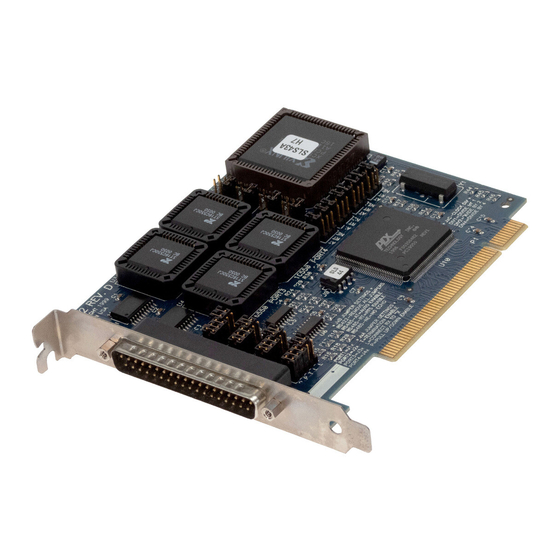
Page 28: Appendix D: Board Layout
4-PORT SERIAL HOST ADAPTER PCI Appendix D: Board Layout Figure D-1. Board Layout. - Page 29 NOTES...
- Page 30 © Copyright 2001. Black Box Corporation. All rights reserved. 1000 Park Drive • Lawrence, PA 15055-1018 • 724-746-5500 • Fax 724-746-0746...
Need help?
Do you have a question about the IC189C and is the answer not in the manual?
Questions and answers