
Subscribe to Our Youtube Channel
Related Manuals for Black Box IC102C-R2


Summary of Contents for Black Box IC102C-R2
- Page 1 © Copyright 2000. Black Box Corporation. All rights reserved. 1000 Park Drive • Lawrence, PA 15055-1018 • (724) 746-5500 • Fax (724) 746-0746...
- Page 2 Order toll-free in the U.S. 24 hours, 7 A.M. Monday to midnight Friday: 877-877-BBOX FREE technical support, 24 hours a day, 7 days a week: Call 724-746-5500 or fax 724-746-0746 SUPPORT Mail order: Black Box Corporation, 1000 Park Drive, Lawrence, PA 15055-1018 INFORMATION Web site: www.blackbox.com • E-mail: info@blackbox.com...
- Page 3 4-PORT CARD SERIAL HOST ADAPTER WITH ISP...
- Page 4 FCC INFORMATION FEDERAL COMMUNICATIONS COMMISSION CANADIAN DEPARTMENT OF COMMUNICATIONS RADIO FREQUENCY INTERFERENCE STATEMENTS This equipment generates, uses, and can radiate radio frequency energy and if not installed and used properly, that is, in strict accordance with the manufacturer’s instructions, may cause interference to radio communication. It has been tested and found to comply with the limits for a Class A computing device in accordance with the specifications in Subpart J of Part 15 of FCC rules, which are designed to provide reasonable protection against such interference when the equipment is...
- Page 5 4-PORT CARD SERIAL HOST ADAPTER WITH ISP NORMAS OFICIALES MEXICANAS (NOM) ELECTRICAL SAFETY STATEMENT INSTRUCCIONES DE SEGURIDAD 1. Todas las instrucciones de seguridad y operación deberán ser leídas antes de que el aparato eléctrico sea operado. 2. Las instrucciones de seguridad y operación deberán ser guardadas para referencia futura.
- Page 6 NOM STATEMENT 10. El equipo eléctrico deber ser situado fuera del alcance de fuentes de calor como radiadores, registros de calor, estufas u otros aparatos (incluyendo amplificadores) que producen calor. 11. El aparato eléctrico deberá ser connectado a una fuente de poder sólo del tipo descrito en el instructivo de operación, o como se indique en el aparato.
- Page 7 4-PORT CARD SERIAL HOST ADAPTER WITH ISP EMC Directive Statement Products bearing the CE label fulfill the requirements of the EMC directive (89/336/EEC) and of the low-voltage directive (73/23/EEC) issued by the European Commission. To obey these directives, these European standards must be met: •...
-
Page 8: Table Of Contents
CONTENTS Contents Chapter Page 1. Specifications ......................8 2. Introduction ......................9 2.1 Overview ......................9 2.2 Technical Description ..................10 2.2.1 Interrupt Status Port (ISP) ..............10 2.2.2 Connector Pin Assignments ..............11 3. Configuration ......................13 3.1 Address Selection....................13 3.2 Jumper Selections ..................15 3.3 IRQ Selection ....................15 3.4 Interrupt Modes....................16 3.5 Clock Modes....................17 3.6 Baud Rates and Divisors for the “DIV1”... -
Page 9: Specifications
Number of Ports — Connectors — DB37 to (4) DB25 male Communications Chip — IC102C-R2: 16554 UART; IC180C: 16950 UART Manufacturing — IPC 610-A Class-III standards are adhered to with a 0.1 visual A.Q.L. and 100% functional testing. This circuit board is built to UL ®... -
Page 10: Introduction
RS-232 electrical interface. The Adapter is shipped with the items listed below. If any of these items are missing or damaged, call Black Box. • The 4-Port Card Serial Host Adapter with ISP, •... -
Page 11: Technical Description
4-PORT CARD SERIAL HOST ADAPTER WITH ISP 2.2 Technical Description The IC102C-R2 Adapter uses the 16554 UART. This chip features programmable baud rate, data format, interrupt control, and a 16-byte input and output FIFO, and is functionally 4 16550 UARTs. The IC180C uses 16950 UARTs, which feature a 128-byte FIFO. -
Page 12: Connector Pin Assignments
CHAPTER 2: Introduction 2.2.2 C ONNECTOR SSIGNMENTS DB25 (RS-232 DTE) Signal Name Pin # Mode Ground Transmit Data Output Request To Send Output Data Terminal Ready Output Receive Data Input Clear To Send Input Data Set Ready Input Data Carrier Detect Input Ring Indicator Input... - Page 13 4-PORT CARD SERIAL HOST ADAPTER WITH ISP DB37 Port #...
-
Page 14: Configuration
CHAPTER 3: Configuration 3. Configuration The 4-Port Card Serial Host Adapter with ISP contains several jumper straps that must be set for proper operation. 3.1 Address Selection Each port on the 4-Port Card Serial Host Adapter with ISP occupies eight consecutive I/O locations. - Page 15 4-PORT CARD SERIAL HOST ADAPTER WITH ISP There’s also a second mode of address selection. In this mode, the DIP switch sets the base address and the Adapter occupies 32 consecutive I/O locations. The table below illustrates the location of each port and its relationship to the other ports. NOTE For switches 1–5 to become active, switches 6, 7, and 8 must be set in the “On”...
-
Page 16: Jumper Selections
CHAPTER 3: Configuration Table 3-3. Port to connector Port # Connector Location Address Example (Base=2E0) Base+0 2E0-2E7 Base+8 2E8-2EF Base+16 2F0-2F7 Base+24 2F8-2FF 3.2 Jumper Selections For ease of configuration, the headers are grouped by port. Port 1 headers have a “J1”... -
Page 17: Interrupt Modes
4-PORT CARD SERIAL HOST ADAPTER WITH ISP NOTE Most DOS communications software applications default COM3: to IRQ4 and COM4: to IRQ3. This requires the sharing of interrupts between COM1: and COM3:, and between COM2: and COM4:. While this is the default, it is not always the best setting. -
Page 18: Clock Modes
CHAPTER 3: Configuration Set the jumpers to “S” for shared interrupt mode on all blocks sharing an IRQ except one. Set that port block for “M.” This provides the pull-down resistor circuit that makes sharing IRQs possible. If you are using more than one 4-Port Card Serial Host Adapter with ISP or a compatible adapter in a bus, you should only have one port set to “M.”... - Page 19 4-PORT CARD SERIAL HOST ADAPTER WITH ISP To select the baud rates commonly associated with COM ports (for example, 2400, 4800, 9600, 19.2,...115.2 Kbps) place the jumper in the divide by 4 mode (silk- screened DIV4). DIV1 DIV2 DIV4 Figure 3-5. Clocking mode “Divide By 4.” To double these rates up to a maximum rate of 230.4 Kbps, place the jumper in the divide by 2 (silk-screened DIV2) position.
-
Page 20: Baud Rates And Divisors For The "Div1" Mode
CHAPTER 3: Configuration 3.6 Baud Rates and Divisors for the “DIV1” Mode The following table shows some common data rates and the rate you should choose to match them if using the Adapter in the DIV1 mode. For this data rate... choose this data rate 1200 bps 300 bps... -
Page 21: Baud Rates And Divisors For The "Div2" Mode
4-PORT CARD SERIAL HOST ADAPTER WITH ISP 3.7 Baud Rates and Divisors for the “DIV2” Mode The following table shows some common data rates and the rate you should choose to match them if using the Adapter in the DIV2 mode. For this data rate... -
Page 22: Installation
CHAPTER 4: Installation 4. Installation The 4-Port Card Serial Host Adapter with ISP can be installed in any of the PC expansion slots. The Adapter contains several jumper straps for each port that must be set for proper operation—see Chapter 3. IMPORTANT You MUST set up the operating system BEFORE you physically install the Card. - Page 23 4. Gently insert the Adapter into the slot. Make sure that the Adapter is seated properly. 5. For the IC102C-R2 or IC180C connect the DB37 female connector end of the octopus cable to the DB37 male connector on the card.
-
Page 24: Troubleshooting
CHAPTER 5: Troubleshooting 5. Troubleshooting A Serial Utility Diskette is supplied with the Adapter and will be used in the troubleshooting procedures. By using this diskette and following these simple steps, most common problems can be eliminated without the need to call Technical Support. -
Page 25: Appendix A: The Rs-232 Interface
4-PORT CARD SERIAL HOST ADAPTER WITH ISP Appendix A. The RS-232 Interface Quite possibly the most widely used communication standard is RS-232. This implementation has been defined and revised several times and is often referred to as RS-232-C/D/E or EIA/TIA-232-C/D/E. It is defined as “Interface between Data Terminal Equipment and Data Circuit-Terminating Equipment Employing Serial Binary Data Interchange.”... -
Page 26: Appendix B: Asynchronous Communications
APPENDIX B: Asynchronous Communications Appendix B. Asynchronous Communications Serial data communications implies that individual bits of a character are transmitted consecutively to a receiver that assembles the bits back into a character. Data rate, error checking, handshaking, and character framing (start/stop bits) are pre-defined and must correspond at both the transmitting and receiving ends. - Page 27 4-PORT CARD SERIAL HOST ADAPTER WITH ISP An extra bit used for error detection is often appended before the stop bits. This special bit is called the parity bit. Parity is a simple method of determining if a data bit has been lost or corrupted during transmission. There are several methods for implementing a parity check to guard against data corruption.
-
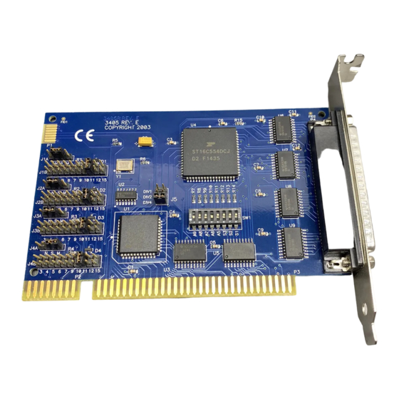
Page 28: Appendix C: Circuit-Board Diagram
APPENDIX C: Circuit-Board Diagram Appendix C. Circuit-Board Diagram 3.10 in. 3.40 in.
Need help?
Do you have a question about the IC102C-R2 and is the answer not in the manual?
Questions and answers