Table of Contents
Advertisement
Quick Links
Advertisement
Table of Contents

Related Manuals for Martindale Electric PSI4000


Summary of Contents for Martindale Electric PSI4000
- Page 1 PSI4000 / PSI4300 PHASE SEQUENCE INDICATOR nstructIon anual...
- Page 2 Where applicable other safety measures such as use of protective gloves, goggles etc. should be employed. If the equipment is used in a manner not specified by Martindale Electric, the protection provided by the equipment may be impaired. Please keep these instructions for future reference. Updated instructions and product information are available at: www.martindale-electric.co.uk...
-
Page 3: Table Of Contents
Thank you for buying one of our products. For safety and full understanding of its benefits please read this manual before use. Technical support is available from 01923 441717 and support@ martindale-electric.co.uk. CONTENTS Introduction Inspection Description Accessories Battery Installation Product Specific Safety Information Precautions Operation Description of Press Buttons and Indicators... -
Page 4: Introduction
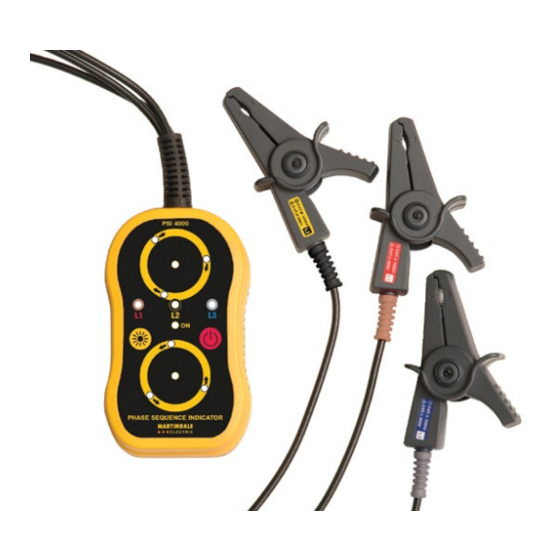
If there is any damage then consult your distributor immediately. 1.2 Description The PSI4000 and PSI4300 are Non-Contact Phase Detector and Phase Sequence Indicators with the following features: Non-contact connection clips to enhance user safety during testing and also allow the testing of insulated conductors. -
Page 5: Product Specific Safety Information
2. PRODUCT SPECIFIC SAFETY INFORMATION Measurement Category III (CAT III) is applicable to test and measuring equipment connected to the distribution part of the building’s low-voltage MAINS installation. Measurement Category IV (CAT IV) is applicable to test and measuring equipment connected at the source of the building’s low- voltage MAINS installation. 2.1 Precautions This product has been designed with your safety in mind, but please pay attention to the following warnings and cautions before use. -
Page 6: Operation
or missing are actually dead. The phase to earth voltage of the suspected phase could be < 75V, or two or all three sensor clips could be sensing the same phase, thereby giving incorrect test indications. Caution Avoid severe mechanical shock or vibration and extreme temperature. -
Page 7: Low Battery Indication
If the ON LED flashes when the unit is turned on, the batteries are low and need to be replaced (see section 4.1 battery replacement). 3.3 Auto Power Off If the PSI4000/PSI4300 is inactive for a period of approximately 5 minutes it will automatically power down. 3.4 Enhanced Brightness Press the button to increase the brightness of the LED’s when... -
Page 8: Testing Considerations
Do not pull the sensor clip wires to remove the sensor clips from the cables under test. This may break or damage the sensor clip wires. 3.6 Proving Check Before and after use, prove the function of the PSI4000 / PSI4300 by performing steps 1 to 4 below: 1. Press the button to turn on the instrument. -
Page 9: Testing A 3 Phase Distribution System
2. To determine phase presence and phase sequence, attach the three sensor clips of the PSI4000 / PSI4300 to the three separate unshielded phase cables of the 3 phase electrical distribution system to be tested, whilst referring to figure 1 and observing the testing considerations of section 3.6. - Page 10 Note 2: The colours of the cables under test cannot be relied upon to confirm the expected phases. Table 1 PSI4000 Indication PSI4300 Indication Wiring Condition Respective phase L1, L2 or L3 LED’s illuminated.
-
Page 11: Wiring Colour Coding
Colours 4. MAINTENANCE 4.1 Battery Replacement To avoid shock or injury, disconnect the PSI4000 / PSI4300 sensor clips from any external circuits before proceeding. The battery compartment is underneath the unit and can be accessed by undoing the screw securing the battery cover, and lifting it off. -
Page 12: Cleaning
4.3 Repair & Service There are no user serviceable parts in this unit other than those that may be described in section 4. Return to Martindale Electric if faulty. Our service department will quote promptly to repair any fault that occurs outside the guarantee period. - Page 13 5. WARRANTY AND LIMITATION OF LIABILITY This Martindale product is warranted to be free from defects in material and workmanship under normal use and service. The warranty period is 2 years and begins on the date of receipt by the end user.
-
Page 14: Specifications
Specification PSI4000/PSI4300 Phase Sequence Indicator PSI4000 clockwise rotation PSI4300 anti-clockwise rotation Measurement principle: Static induction Input voltage range: 75V to 1000V AC (phase to earth) Input frequency range: 45Hz to 65Hz Location: Indoor use Altitude: up to 2000m Temperature & Humidity: Operating: -10°C to 50°C ≤ 80% R.H. - Page 15 Weight: 370g approx (batteries included) Includes: 4 x 1.5V alkaline batteries, soft case & instructions Safety: Conforms to BS EN 61010-1, BS EN 61557-1 & BS EN 61557-7 CAT III 1000V, CAT IV 600 V. Class II Reinforced insulation EMC: Conforms to BS EN 61326-1...
- Page 16 Ver. C1.3 Due to policy of continuous development, Martindale Electric reserves the right to alter equipment specification and description outlined in this document without prior notice. No part of this document shall be deemed to be part of any contract for the equipment unless specifically referred to as an inclusion within such contract.
Need help?
Do you have a question about the PSI4000 and is the answer not in the manual?
Questions and answers