Advertisement
Quick Links
WIRELESS HAND-HELD FIRE
DETECTOR
«Ladoga IPR-RK»
Installation Guide
1 Product overview
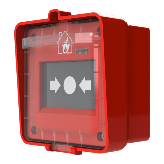
1.1 Wireless hand-held fire Detector «Ladoga IPR-RK» (hereinafter,
the Detector) is designed for remote manual activation of a fire alarm
signal at the control panel (hereinafter, the CP) via wireless two-way
communication by the «Rielta-Contact-R
1.2 The Detector generates the fire alarm signal (responds) upon
pressing the actuator.
1.3 The Detector operates within 433.05 – 434.79 MHz frequency
range. The radiated power of the Detector does not exceed 10 mW.
1.4 Two frequencies are used for wireless signal exchange with the
CP: the main operating frequency and the reserve one. The Detector
switches to the reserve operating frequency automatically.
1.5 The wireless signal exchange is initiated by the Detector with the
following rates: every 10 sec, 15 sec, 30 sec, 60 sec, 300 sec, 600 sec.
Data exchange rates are chosen during the Detector logging in CP. The
alarm messages are transmitted immediately.
1.6 The Detector is powered by two lithium batteries (the main one
and the backup one) type СR123A.
1.7 The Detector state is displayed by two LED indicators: red and
green.
1.8 At the scheduled communication sessions the following messages
can be delivered to CP:
- «Norm
– in absence of other types of messages;
»
- «Fire
– upon the actuator pressing;
»
- «Tamper
– under the wall or case tampering;
»
- «Main power supply low battery
voltage drops below (2,1±1) V;
- «Backup power supply low battery
supply voltage drops below (2,1±1) V.
1.9 The Detector ensures safe operation continuously around the clock.
1.10 The Detector is resistant to the influence of electrical fast transient
bursts, electrostatic discharges and radio-frequency electromagnetic
fields.
1.11 The Detector ensures safe operation when subjected to:
- vibration at 0.5 g acceleration within 10 to 150 Hz frequency range;
- straight mechanical blows with impact energy up to 1.9 J.
2 Specifications
Table 1
Parameter
Operating temperature
Permissible relative air humidity at temperature
+40 °С
Dimensions, maximum
Weight of the Detector (without batteries),
maximum
IP rating
Operation time upon preset wireless signal
exchange rate 60 sec or more, normal climatic
conditions and indication disabled, not less than:
- from the main battery
- from the reserve battery
Average service life, not less than
3 Scope of Delivery
Each Detector unit package contains the items listed in Table 2.
Table 2
Name
Wireless Hand-held Fire Detector «Ladoga IPR-RK»
Key
Screw 3-3х30.016
Nylon screw plug «SORMAT» NAT 5x25
СR123A lithium power supply battery
Wireless Hand-held Fire Detector «Ladoga IPR-RK». Installation
Guide
* - installed in case
protocol.
»
– if the main battery power supply
»
– if the reserve battery power
»
Value
minus 20 ... +55 °С
up to 93 %
106 х 98 х 70 mm
0,2 kg
IP54
10 years
2 months
10 years
3 pcs.
3 pcs.
1 copy
4 Design of the Detector
The Detector consists of case and printed circuit board (PCB). The
case of the Detector comprises base, actuator assembly unit and
transparent protective cover. On the PCB front side (1) the following
elements are located: LED indicators (2), antenna (3), RESET contacts
(5), case tamper (6), main power supply battery holder (7), reserve
power supply battery holder (8) . Wall tamper is located on the reverse
side of the PCB. The PCB is fastened to the base of the Detector case
by latch (4). On the base the following elements are located: sealing
point (9), two main fixing holes (10) and additional openable hole for
fixing (12). An additional openable fixing hole (11) can be used for
wall tamper control.
1
BACKUP
8
7
MAIN
+
IPR-RK V10.1
a) The base with the PCB
installed
5 LED Indication
LED indicators modes are listed in the Table 3.
Table 3
The Detector State
«
Binding» mode
«
Binding» procedure
finishing
«
Identification» indication
«
Fire» message delivery
confirmation
«
Fire»
No communication with
CP
Communication quality
appraising
«
Norm»
«Identification
from CP and stays on for 15 minutes under the condition of «Fire
message absence or until case is opened.
6 Binding with the CP
The binding procedure is intended for logging of the Detector in the
CP and for transmission of service information to it.
6.1 Prepare the CP for the Detector logging in accordance to the CP
Installation Guide.
6.2 At first install the backup power supply battery into the holder (8),
and then install the main power supply battery into the holder (7), or
remove isolators.
6.3 LED indicator blinking green means, that the Detector is in the
«Binding
mode.
»
6.4 In case of the mentioned above LED indication absence, short-
circuit the RESET contacts (5) for 2 – 3 sec.
6.5 After a successful binding with the CP, the red LED indicator is
lighting red for 2 – 3 sec.
6.6 The time during which the Detector operates in the «Binding»
mode is limited to 100 sec. To restart the «Binding» mode, short-circuit
Qnt.
the RESET contacts for 2 – 3 sec.
1 pc.
7 Switching ON and Setting Up
1 pc.
7.1 To activate the Detector, open transparent cover and press the
actuator. In the meantime the actuator recesses and fixes itself in a
pressed position, and the Detector generates «Fire
2 pc.
delivery confirmation from the CP and further Detector operation in the
«Fire
generation mode is accompanied by the relevant LED indication
»
listed in the Table 3.
2
+
3
4
5
RESET
6
b) The base without PCB
Figure 1
Indication
Green LED indicator
periodical blinking
Red LED indicator lighting
for 2 – 3 sec
Red and green indicators
alternate blinking
Green LED indicator
lighting for 2 – 3 sec
Red LED indicator blinking
with 2 sec period
Red LED indicator blinking
with 20 sec period
«
See sect.
Communication Quality Appraising»
Green LED indicator
short blinking with 20 sec
period
indication is switched on upon the relevant command
»
9
10
11
12
Notes
The Detector
logging in the CP
Confirmation from
the CP is received
«
After
Fire»
message delivery
confirmation
«
Tamper» message
absence
»
message. Message
»
Advertisement

Related Manuals for Rielta Ladoga IPR-RK


Summary of Contents for Rielta Ladoga IPR-RK
- Page 1 Installation Guide wall tamper control. 1 Product overview 1.1 Wireless hand-held fire Detector «Ladoga IPR-RK» (hereinafter, the Detector) is designed for remote manual activation of a fire alarm BACKUP signal at the control panel (hereinafter, the CP) via wireless two-way communication by the «Rielta-Contact-R...
- Page 2 Detector should get the » frequency range from 10 to 120 per minute or 15 000 strikes; command «Arm from the CP in accordance to the «Rielta-Contact-R » » - ambient temperature range minus 50 ... +50 °С;...
Need help?
Do you have a question about the Ladoga IPR-RK and is the answer not in the manual?
Questions and answers