
Related Manuals for Horizon Hobby E-FLITE Cirrus SR22T


Summary of Contents for Horizon Hobby E-FLITE Cirrus SR22T
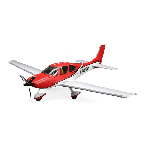
- Page 1 Cirrus SR22T 1.5m EFL15950 EFL15975 Instruction Manual Bedienungsanleitung Manuel d’utilisation Manuale di Istruzioni...
- Page 2 This product is not intended for use by children without direct adult supervision. Do not use with incompatible components or alter this product in any way outside of the instructions provided by Horizon Hobby, LLC. This manual contains instructions for safety, operation and maintenance.
-
Page 3: Table Of Contents
Included / Recommended Equipment Specifications 59 in (1498mm) Motor: BL10 Brushless Outrunner, 800Kv 14 pole Installed Installed (EFLM17552) ESC: Avian 60 Amp Brushless Smart ESC, 3S-6S Installed Installed (SPMXAE1060) Servos: Aileron: (2) Spektrum 330R; 187mm Lead Elevator: (1) Spektrum 330R; 187mm Lead Installed Installed Rudder: (1) Spektrum 330R;... -
Page 4: Transmitter Setup
Transmitter Setup DX Series Transmitter Setup WARNING: If your transmitter allows it, enable the throttle cut feature. Always engage throttle cut before approaching the aircraft. 7. Set D/R (Dual Rate) and Expo; Elevator Set Switch: SWITCH C WARNING: Never assign Aux 2 to SAFE Select during transmitter setup High Rates: 100%, - Low Rates 70% with any model transmitter. -
Page 5: Pnp Receiver Selection And Installation
PNP Receiver Selection and Installation The recommended receiver for this aircraft is the Spektrum AR637T. If you choose AR637T Port Assignments to install a different receiver, ensure that it is at least a 6-channel full range receiver. Refer to the manual of your chosen receiver for correct installation and BND/PRG = BIND 4 = Rudder operation instructions. -
Page 6: Binding
Binding General Binding Tips and Failsafe • The included receiver has been specifically programmed • Once bound, the receiver will retain its bind settings for operation of this aircraft. Refer to the receiver manual for that transmitter until you re-bind. for correct setup if the receiver is replaced. -
Page 7: Safe ® Select Switch Designation Bnf Basic
SAFE Select Switch Designation BNF Basic ® Stick Inputs Assigning a Switch 1. Power on the transmitter. Once SAFE Select is enabled, you can choose to fly in SAFE mode full-time, or assign a switch. Any switch on any channel between 5 and 9 can be used on your 2. -
Page 8: Model Assembly
Model Assembly Landing Gear Installation Main Gear 1. Install the landing gear assemblies (A) into the mounting locations on the sides of the fuselage as shown. 2. Secure the landing gear into place with the four M3 x 8mm screws (B) as shown. -
Page 9: Model Assembly Continued
Model Assembly Continued Nose Gear Centering Observe the following steps to fine tune the nose gear neutral position. 1. With the radio control system powered on, the rudder centered, and the rudder trim centered, check that the nose gear is centered. Tip: The best way to check that the nose gear and rudder are centered is by rolling the model on a smooth surface. -
Page 10: Scale Accessories Optional
Scale Accessories Optional Scale accessories are each held in place with a single 2 x 6mm self tapping screw using a Phillips screw driver. 2 x 6mm self-tapping button head Flaps Flaps Flaps Control Horn and Servo Arm Settings The table to the right shows the factory settings for the control horns and servo Horns Arms Elevator... -
Page 11: Control Direction Test
If the control surfaces do not respond as shown, DO NOT FLY. Refer to the Troubleshooting Guide for more information. If you need more assistance, contact the appropriate Horizon Hobby Product Support department. If the aircraft responds as shown, continue on to the Flight Control section. -
Page 12: As3X ® Control Response Test
AS3X Control Response Test ® WARNING: Do not perform any testing or maintenance with the propeller Aircraft movement AS3X Reaction installed on the aircraft. Serious injury or property damage could result from the motor starting inadvertently. This test ensures that the AS3X control system is functioning properly. Assemble the aircraft and bind your transmitter to the receiver before performing this test. -
Page 13: Safe Select Flying Tips Bnf
SAFE Select Flying Tips BNF Differences between SAFE Select and AS3X modes When flying in SAFE Select mode the aircraft will return to level flight any time the aileron and elevator controls are at neutral. Applying aileron or elevator control This section is generally accurate but does not take into account flight speed, will cause the airplane to bank, climb or dive. -
Page 14: Servo Service
Servo Service Control Surface Replacement Servo Description Replacement Adhesive Aileron SPMSA330R 9g Sub-Micro Servo 187mm Lead Elevator SPMSA330R 9g Sub-Micro Servo 187mm Lead Deluxe Materials Foam 2 Foam (DLMAD34) Rudder SPMSA330R 9g Sub-Micro Servo 187mm Lead Flaps SPMSA330R 9g Sub-Micro Servo 187mm Lead Troubleshooting Guide AS3X Problem Possible Cause... -
Page 15: Replacement Parts
Problem Possible Cause Solution Control surface, control horn, linkage or servo damage Replace or repair damaged parts and adjust controls Wire damaged or connections loose Do a check of wires and connections, connect or replace as needed Control surface does Transmitter is not bound correctly or the incorrect Re-bind or select correct airplanes in transmitter not move... -
Page 16: Important Federal Aviation Administration (Faa) Information
Important Federal Aviation Administration (FAA) Information If your model aircraft weights more than .55lbs or 250 grams, you are required by Use the QR code below to learn more about the Recreational UAS Safety Test the FAA to register as a recreational flyer and apply your registration number to the (TRUST), as was introduced by the 2018 FAA Reauthorization Bill. -
Page 17: Limited Warranty
(iii) modification of or to any part process found on our website or call Horizon to obtain a Return Merchandise of the Product, (iv) attempted service by anyone other than a Horizon Hobby authorized Authorization (RMA) number. Pack the Product securely using a shipping carton. -
Page 18: Fcc Information
It should be deposited at an appropriate facility to enable recovery and recycling. Cirrus SR22T 1.5m BNF Basic (EFL15950); Hereby, Horizon Hobby, LLC declares that the device is in compliance with the following: EU Radio Equipment Directive... - Page 19 © 2021 Horizon Hobby, LLC. E-flite, Avian, DSM, DSM2, DSMX, Bind-N-Fly, BNF, the BNF logo, Plug-N-Play, AS3X, SAFE, the SAFE logo, ModelMatch, IC5, EC5, and the Horizon Hobby logo are trademarks or registered trademarks of Horizon Hobby, LLC. The Spektrum trademark is used with permission of Bachmann Industries, Inc.
Need help?
Do you have a question about the E-FLITE Cirrus SR22T and is the answer not in the manual?
Questions and answers
Aileron servo needs to be replaced. What's the part number and how do you install it?
The recommended replacement for the aileron servo on the Horizon Hobby E-flite Cirrus SR22T is the HiTec HS-5065MG+ Digital Mighty servo with metal gears. This servo fits directly into place and is already set in the correct direction for installation. AS3X stabilization requires digital servos for the ailerons and elevator, so using this servo ensures compatibility.
This answer is automatically generated