Table of Contents
Advertisement
Available languages
Available languages
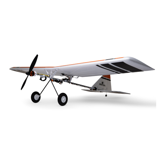
Slow Ultra Stick 1.2m
Instruction Manual
Scan the QR code and select the Manuals and Support quick links from the
product page for the most up-to-date manual information.
Bedienungsanleitung
Scannen Sie den QR-Code und wählen Sie auf der Produktseite die Quicklinks
Manuel d'utilisation
Handbücher und Unterstützung, um die aktuellsten Informationen zu Handbücher.
Manuale di Istruzioni
Scannez le code QR et sélectionnez les liens rapides Manuals and Support sur la
page du produit pour obtenir les informations les plus récentes sur le manuel.
Scannerizzare il codice QR e selezionare i Link veloci Manuali e Supporto dalla
EFL0350
pagina del prodotto per le informazioni manuali più aggiornate.
267459.1 Created 01/23
Advertisement
Chapters
Table of Contents
Troubleshooting

Subscribe to Our Youtube Channel
Related Manuals for Horizon Hobby E-FLITE Slow Ultra Stick 1.2m


Summary of Contents for Horizon Hobby E-FLITE Slow Ultra Stick 1.2m
- Page 1 Slow Ultra Stick 1.2m Instruction Manual Scan the QR code and select the Manuals and Support quick links from the product page for the most up-to-date manual information. Bedienungsanleitung Scannen Sie den QR-Code und wählen Sie auf der Produktseite die Quicklinks Manuel d’utilisation Handbücher und Unterstützung, um die aktuellsten Informationen zu Handbücher.
- Page 2 This product is not intended for use by children without direct adult supervision. Do not use with incompatible components or alter this product in any way outside of the instructions provided by Horizon Hobby, LLC. This manual contains instructions for safety, operation and maintenance.
-
Page 3: Table Of Contents
Included / Recommended Equipment Specifications 46.7 in. (1188 mm) MOTOR: 3513-1100Kv Outrunner Motor, 14 pole (SPMXAM2800) Included ESC: Avian 30-Amp Brushless Smart Lite ESC; 3S-4S, IC3 (SPMXAE30D) Installed Servos: A345SL 9g Sub-Micro Digital Servo: 60mm Lead (SPMSA345SL) Aileron: (1) Installed Rudder: (1) Elevator: (1) Receiver: AR630 DSMX 6-Channel AS3X &... -
Page 4: Model Assembly
Model Assembly Rear Fuselage Section Installation 1. Slide the two fuselage sections together until they click, connecting the front and rear fuselage sections. 2. Secure the sections together with the two included M2 x 14mm button head screws. (Use a #1 Phillips screwdriver) 3. - Page 5 Vertical Stabilizer Installation 1. Slide the vertical stabilizer (A) on the rear fuselage tube until the holes align. 2. There are two pushrods in the parts bag for the rudder and elevator. Choose longer one and use it for the rudder. 3.
- Page 6 Horizontal Stabilizer Installation 1. Ensure the control horn is facing up, then slide the horizontal stabilizer (A) on the rear fuselage tube until the bottom screw holes align. 2. Secure the vertical and horizontal stabilizers using the included M3 x 22mm thumb screw (B). 3.
- Page 7 Tail Wheel Installation 1. Align the tail wheel wire with the recess in the bottom of the rudder. 2. Press the tail wheel wire into the recess until the wire clicks into place. Disassemble in reverse order. Wing Installation 1. Slide the wing tube (A) into the wing. 2.
- Page 8 Wing Installation 1. Align and place the wing retainer (B) on top of the wing. 2. Align the wing with the three pins on the front wing mount, then slide the wing forward into place. 3. Secure the wing to mounts with two included M3 x 22mm thumb screws (C) 4.
-
Page 9: Transmitter Setup
Transmitter Setup WARNING: Enable the throttle cut feature. Always engage throttle cut Computerized Transmitter Setup before approaching the aircraft. Start all transmitter programming with a blank ACRO model (perform a model WARNING: Never assign Aux 2 to SAFE Select during transmitter setup reset), then name the model. -
Page 10: Battery Installation And Esc Arming
Battery Installation and ESC Arming Battery Selection We recommend the 3S 1300mAh 30C Smart Li-Po Battery. Refer to the Optional Parts List for other recommended batteries. If using a battery other than those listed, the battery should be within the range of capacity, dimensions and weight of the Spektrum Li-Po battery packs to fit in the fuselage. -
Page 11: Binding
Binding General Binding Tips and Failsafe • The included receiver has been specifically programmed • Once bound, the receiver will retain its bind settings for operation of this aircraft. Refer to the receiver manual for that transmitter until you re-bind. for correct setup if the receiver is replaced. -
Page 12: Safe ® Select Switch Designation
SAFE Select Switch Designation ® Stick Inputs Assigning a Switch 1. Power on the transmitter. Once SAFE Select is enabled, you can choose to fly in SAFE mode full-time, or assign a switch. Any switch on any channel between 5 and 9 can be used on your 2. -
Page 13: Control Direction Test
Control Direction Test Switch on the transmitter and connect the battery. Use the transmitter to operate Transmitter Command Control SurfaceResponse the aileron, elevator and rudder controls. View the aircraft from the rear when checking the control directions. This model has a built in aileron to rudder mix, when the ailerons are deflected the rudder will move. -
Page 14: As3X Response Test
AS3X Response Test This test ensures that the AS3X ® control system is functioning properly. Assemble Aircraft movement AS3X Reaction the aircraft and bind your transmitter to the receiver before performing this test. 1. Raise the throttle just above 25%, then lower the throttle to activate AS3X. CAUTION: Keep all body parts, hair and loose clothing away from a moving propeller, as these items could become entangled. -
Page 15: Control Surface Centering And Adjusting A Clevis
Control Surface Centering and Adjusting a Clevis IMPORTANT: Perform the Control Direction Test before performing control surface centering. While SAFE is inactive, mechanically center the control surfaces. IMPORTANT: Correct operation of the SAFE system requires sub-trim and trim at 0. After binding a transmitter to the receiver, set the trims and sub-trims to 0, ensure the servo arms are in the correct positions, then adjust the linkages to center the control surfaces. -
Page 16: Center Of Gravity (Cg)
Center of Gravity (CG) The CG location is measured from the leading edge of the wing. This CG location has been determined with the recommended 3S 1300mAh Li-Po battery 115mm +/-5 (SPMX133S30) installed to the front edge of the battery tray. Adjust the battery behind the leading forward or aft as needed to achieve the proper CG location. -
Page 17: Optional Two-Servo Aileron Setup
Optional Two-Servo Aileron Setup 1. Remove the wing from the aircraft. 2. Remove the servo arm screw and the installed servo arm. 3. Removed the servo arm from the z-bend of each pushrod. 4. Remove the 2 screws securing the servo to the wing. 5. -
Page 18: Post Flight
Post Flight 5. Store the flight battery apart from the aircraft and monitor the 1. Disconnect the flight battery from the ESC (required for safety and battery charge. battery life). 6. Make note of the flight conditions and flight results, planning for future flights. 2. -
Page 19: Troubleshooting Guide
Troubleshooting Guide Problem Possible Cause Solution Damaged propeller and spinner, prob adapter or motor Replace damaged parts Extra propeller noise or Propeller is out of balance Balance or replace propeller extra vibration Prop nut is too loose Tighten the prop nut Flight battery charge is low Completely recharge flight battery Propeller installed backwards... -
Page 20: Replacement Parts
Replacement Parts Optional Parts Part # Description Part # Description SPMR8105 DX8e 8 Ch Transmitter Only EFL0351 Right Wing: Slow Ultra Stick SPMR6775 NX6 6 Ch Transmitter Only EFL0352 Left Wing: Slow Ultra Stick EFL0353 Wing Joiner: Slow Ultra Stick SPMR8200 NX8 8 Ch Transmitter Only EFL0354... -
Page 21: Ama National Model Aircraft Safety Code
(iii) modification of or to any part process found on our website or call Horizon to obtain a Return Merchandise of the Product, (iv) attempted service by anyone other than a Horizon Hobby authorized Authorization (RMA) number. Pack the Product securely using a shipping carton. -
Page 22: Contact Information
EFL Slow Ultra Stick Manual 1.2M BNF Basic (EFL0350); Hereby, This appliance is labeled in accordance with European Directive Horizon Hobby, LLC declares that the device is in compliance with the 2012/19/EU concerning waste of electrical and electronic equipment following: EU Radio Equipment Directive 2014/53/EU, RoHS 2 Directive (WEEE). - Page 23 WARNUNG VOR GEFÄLSCHTEN PRODUKTEN: Sollten Sie jemals eine Spektrum Komponente ersetzen wollen, kaufen Sie die benötigten Ersatzteile immer bei Horizon Hobby oder einem von Horizon Hobby autorisierten Händler, um sicherzugehen, dass Sie beste Spektrum Qualität erhalten. Horizon Hobby, LLC lehnt jedwede Haftung, Garantie und Serviceleistung in Bezug auf, aber nicht ausschließlich für, Kompatibilitäts- und Leistungsansprüche von gefälschten Produkten oder Produkten,...
- Page 24 Spezifikationen Enthaltene/Empfohlene Ausrüstung 1188 mm Liefer- MOTOR: 3513-1100 Kv Außenläufermotor, 14-polig (SPMXAM2800) umfang enthalten Geschwindigkeitsregler: Avian 30-Amp Smart Lite Bürstenloser Montiert Geschwindigkeitsregler; 3S-4S, IC3 (SPMXAE30D) Servos: A345SL 9 g Sub-Micro Digital Servo: 60 mm Leitung (SPMSA345SL) Querruder: (1) Montiert Ohne Akku: 801 g (28,2oz) Seitenruder: (1) Höhenruder: (1) Mit 3S 1300mAh Akku:...
-
Page 25: Zusammenbau Des Modells
Zusammenbau des Modells Montage des hinteren Rumpfbereichs 1. Die beiden Rumpfteile zusammenschieben, bis sie einrasten und das vordere und hintere Rumpfteil verbinden. 2. Die Teile mit den beiden beiliegenden M2 x 14mm Kopfschrauben befestigen. (Einen #1 Phillips-Schraubenzieher verwenden) 3. Die Stecker des Nivellierservo sind mit einer silbernen Kennzeichnung versehen. - Page 26 Montage des Seitenleitwerks 1. Schieben Sie das vertikale Leitwerk (A) auf das hintere Rumpfrohr, bis die Löcher übereinander liegen. 2. In der mitgelieferten Tasche befinden sich zwei Schubstangen für das Seiten- und Höhenruder. Wählen Sie ein längeres und nehmen es für das Seitenruder. 3.
- Page 27 Montage des Höhenleitwerks 1. Darauf achten, dass das Steuerhorn nach oben zeigt, und dann das Höhenleitwerk (A) auf das hintere Rumpfrohr schieben, bis die unteren Schraubenlöcher übereinstimmen. 2. Die beiden horizontalen Stabilisatorteile mit der mitgelieferten M3 x 22 mm Daumenschraube (B) befestigen. 3.
- Page 28 Montage des Spornrads 1. Richten Sie den Heckraddraht auf die Aussparung an der Unterseite des Seitenruders aus. 2. Drücken Sie den Heckraddraht in die Aussparung, bis der Draht einrastet. Das Zerlegen erfolgt in der umgekehrten Reihenfolge. Montage der Tragfläche 1. Das Steckungsrohr (A) in die Tragfläche schieben. 2.
- Page 29 Montage der Tragfläche 1. Die Tragflächenhalterung (B) an der Oberseite der Tragfläche ausrichten und platzieren. 2. Die Tragflächen mit den drei Stiften an der vorderen Flügelhalterung ausrichten und dann nach vorne schieben. 3. Die Tragfläche mit den zwei mitgelieferten M3 x 22 mm Flügelschraube (C) am Rumpf befestigen.
-
Page 30: Senderkonfiguration
Senderkonfiguration WARNUNG: Die Gasabschaltungsfunktion aktivieren. Immer die Computergestützte Senderkonfiguration Gasabschaltung aktivieren, bevor Sie sich dem Flugzeug nähern. Die gesamte Senderprogrammierung mit einem leeren ACRO-Modell (eine WARNUNG: Niemals Aux 2 SAFE Select während Senderkonfiguration mit Zurücksetzung des Modells durchführen) beginnen, dann das Modell benennen. beliebigem Modellsender zuweisen. -
Page 31: Montage Des Akkus Und Aktivierung Des Geschwindigkeitsreglers
Montage des Akkus und Aktivierung des Geschwindigkeitsreglers Wahl des Akkus Wir empfehlen den 3S 1300mAh 30C Smart Li-Po-Akku. Siehe Optionale Teileliste zu weiteren empfohlenen Akkus. Wird ein anderer als die aufgeführten Akkus verwendet, dann sollte der Akku in Leistung, Abmessungen und Gewicht dem Spektrum Li-Po-Akkupack entsprechen, damit er in den Rumpf passt. -
Page 32: Binden
Binden Allgemeine Tipps zur Bindung • Der mitgelieferte Empfänger wurde speziell für den Betrieb dieses Fluggeräts • Nach erfolgter Bindung behält der Empfänger seine Bindungseinstellungen programmiert. Nach dem Austausch des Empfängers sind die Anweisungen für den Empfänger bei, bis eine neue Bindung erfolgt. zur ordnungsgemäßen Einrichtung dem Empfängerhandbuch zu entnehmen. -
Page 33: Schalterbelegung Von Safe ® Select
Schalterbelegung von SAFE Select ® Stick Inputs [Hebeleingaben] Zuweisen eines Schalters 1. Schalten Sie den Sender ein. Sobald SAFE Select aktiviert ist, können Sie sich dafür entscheiden, Vollzeit im 2. Schalten Sie das Fluggerät ein. SAFE-Modus zu fliegen, oder einen Schalter zuweisen. Jeder Schalter auf jedem 3. -
Page 34: Integrierte Geschwindigkeitsregler-Telemetrie
Integrierte Geschwindigkeitsregler-Telemetrie Telemetrie-Konfiguration Dieses Flugzeug ist im Geschwindigkeitsregler und Empfänger mit Telemetrie- Technologie ausgestattet, die Informationen wie Motordrehzahl, Spannung, 1. Beginnen Sie mit dem an den Empfänger gebundenen Sender. Motorstrom, Gaseinstellung (%) und FET-Temperatur (Geschwindigkeitsregler) 2. Schalten Sie den Sender ein. liefern kann. -
Page 35: As3X-Kontrolle Lenktest
AS3X-Kontrolle Lenktest Dieser Test stellt sicher, dass das AS3X -Steuersystem ordnungsgemäß ® Flugzeug bewegung AS3X Reaktion funktioniert. Das Flugzeug zusammenbauen und Sender am Empfänger binden, ehe dieser Test durchgeführt wird. 1. Gashebel bis kurz über 25 % heben, dann Gashebel senken, um die AS3X- Technologie zu aktivieren. -
Page 36: Zentrieren Der Steuerflächen Und Anpassen Eines Gabelkopfs
Zentrieren der Steuerflächen und Anpassen eines Gabelkopfs IMPORTANT: Perform the Control Direction Test before performing control surface centering. While SAFE is inactive, mechanically center the control surfaces. IMPORTANT: Correct operation of the SAFE system requires sub-trim and trim at 0. After binding a transmitter to the receiver, set the trims and sub-trims to 0, ensure the servo arms are in the correct positions, then adjust the linkages to center the control surfaces. -
Page 37: Der Schwerpunkt (Cg)
Der Schwerpunkt (CG) Die CG-Position wird von der Vorderkante des Flügels gemessen. Die Position des Schwerpunkts wurde mit dem empfohlenen 3S 1300 mAh Li-Po-Akku 115mm +/-5 (SPMX133S30) bestimmt, der an der Vorderkante der Akkuhalterung montiert hinter der Vorder- wurde. Den Akku bei Bedarf nach vorn oder hinten ausrichten, um den korrekten kante. -
Page 38: Wahlweise Zwei-Servo-Querrudereinstellung
Wahlweise Zwei-Servo-Querrudereinstellung 1. Die Tragfläche vom Fluggerät entfernen. 2. Die Schraube des Servoarms und den eingebauten Servoarm entfernen. 3. Der Servoarm wurde vom Z-Bogen der beiden Schubstangen entfernt. 4. Entfernen Sie die 2 Schrauben, mit denen das Servo an der Tragfläche befestigt ist. -
Page 39: Nach Dem Flug
Nach dem Flug 5. Den Flug-Akku getrennt vom Flugzeug lagern und den Akku-Ladezustand 1. Den Flug-Akku vom Geschwindigkeitsregler trennen (für die Sicherheit und überwachen. die Lebensdauer des Akkus erforderlich). 6. Mit Blick auf die Planung zukünftiger Flüge, die Flugbedingungen und 2. -
Page 40: Fehlerbehebung
Fehlerbehebung Problem Mögliche Ursache Lösung Die Steuerungen mit Gashebel und Gastrimmung auf niedrigster Einstellung Gas nicht im Leerlauf und/oder Gastrimmung zu hoch zurücksetzen Flugzeug reagiert nicht Verfahrweg des Gasservo liegt unter 100 % Sicherstellen, dass Verfahrweg des Gasservos 100 % oder höher ist auf Gas, aber auf alle anderen Steuerungen Gaskanal ist umgekehrt... -
Page 41: Ersatzteile
Ersatzteile Optionale Teile Teile-Nr. Beschreibung Teile-Nr. Beschreibung SPMR8105 Nur NX8e-Sender mit 8 Kanälen EFL0351 Rechter Flügel: Slow Ultra Stick SPMR6775 Nur NX6 6-Kanal-Sender EFL0352 Linker Flügel: Slow Ultra Stick SPMR8200 Nur NX8-Sender mit 8 Kanälen EFL0353 Flügelverbindung: Slow Ultra Stick SPMXC2080 Smart S1100 G2 Wechselstrom-Ladegerät, 1x100 W EFL0354 Steckungsrohr: Slow Ultra Stick... -
Page 42: Haftungsbeschränkung
Garantiezeitraum führen. Dieses Produkt ist nicht für den Gebrauch durch Kinder ohne die Aufsicht Exklusive Garantie Horizon Hobby LLC (Horizon) garantiert, dass dasgekaufte Produkt eines Erziehungsberechtigten vorgesehen. Die Anleitung enthält Sicherheitshinweise frei von Material- und Montagefehlern ist. Der Garantiezeitraum entspricht den und Vorschriften sowie Hinweise für die Wartung und den Betrieb des Produktes. -
Page 43: Garantie Und Service Kontaktinformationen
EFL Slow Ultra Stick Manual 1.2M BNF Basic (EFL0350); ; Hiermit Elektro- und Elektronik-Altgeräte (WEEE) gekennzeichnet. Dieses erklärt Horizon Hobby, LLC, dass das Gerät den folgenden Richtlinien Symbol weist darauf hin, dass dieses Produkt kein normaler entspricht: EU-Richtlinie über elektromagnetische Verträglichkeit 2014/30/EU, Haushaltsabfall ist, sondern in einer entsprechenden Sammelstelle für... - Page 44 This product is not intended for use by children without direct adult supervision. Do not use with incompatible components or alter this product in any way outside of the instructions provided by Horizon Hobby, LLC. This manual contains instructions for safety, operation and maintenance.
- Page 45 Caractéristiques Équipement inclus/recommandé 1188 mm MOTEUR : Moteur à cage tournante, 3513-1 100 kV, 14 pôles Inclus (SPMXAM2800) Variateur ESC : ESC Avian sans balais 30 A Smart Lite ; 3S-4S, IC3 Installé (SPMXAE30D) Servos : Servo 9 g Sub-Micro Digital A345SL : Câble de 60 mm (SPMSA345SL)Aileron : (1) Installé Gouverne de direction : (1) Gouverne de profondeur : (1) Sans batterie : 801 g Récepteur : récepteur de télémétrie AS3X/SAFE 6 canaux AR630...
-
Page 46: Assemblage Du Modèle
Assemblage du modèle Installation de la section arrière du fuselage 1. Faites glisser les deux sections du fuselage ensemble jusqu’à ce qu’elles s’enclenchent, reliant ainsi les sections avant et arrière du fuselage. 2. Fixez les sections ensemble avec les deux vis à tête bombée M2 x 14 mm incluses. - Page 47 Installation du stabilisateur vertical 1. Faites glisser le stabilisateur vertical (A) sur le tube arrière du fuselage jusqu’à ce que les orifices s’alignent. 2. Il y a deux barres de liaison dans le sachet des pièces pour la gouverne de direction et la gouverne de profondeur.
- Page 48 Installation du stabilisateur horizontal 1. Assurez-vous que le guignol de commande est orienté vers le haut, puis faites glisser le stabilisateur horizontal (A) sur le tube arrière du fuselage jusqu’à ce que les trous des vis inférieurs soient alignés. 2. Fixez les stabilisateurs vertical et horizontal en position à l’aide des vis à oreilles M3 x 22 mm (B) incluses.
- Page 49 Installation de la roulette de queue 1. Alignez le fil de la roue de queue avec la cavité au bas de la gouverne de direction. 2. Enfoncez le fil de la roue de queue dans la cavité jusqu’à ce que le fil s’enclenche.
- Page 50 Installation de l’aile 1. Alignez l’aile avec les trois broches sur le support d’aile avant, puis faites glisser l’aile vers l’avant pour la mettre en position. 2. Alignez et placez la bague (B) jusqu’au sommet de l’aile. 3. Fixez l’aile au fuselage avec les deux vis à oreilles M3 x 22 mm incluses (C) 4.
-
Page 51: Paramétrage De L'émetteur
Paramétrage de l’émetteur Configuration informatisée de l’émetteur AVERTISSEMENT : Activez la fonction Throttle Cut (Arrêt du moteur). Activez toujours la coupure des gaz avant d’approcher l’appareil. Démarrez toutes les programmations de l’émetteur avec un modèle vierge ACRO (effectuez une réinitialisation du modèle), puis nommez le modèle. AVERTISSEMENT : N’affectez jamais Aux 2 à... -
Page 52: Installation De La Batterie Et Armement Du Variateur Esc
Installation de la batterie et armement du variateur ESC Choix de la batterie Nous recommandons la batterie Li-Po Smart 3S 1 300 mAh 30C. Consultez la liste des pièces disponibles en option pour connaître les autres batteries recommandées. Si vous utilisez une autre batterie que celles indiquées, elle doit être dans la même gamme de capacité, de dimensions et de poids que les packs de batteries Spektrum Li-Po pour s’insérer dans le fuselage. -
Page 53: Affectation (Binding)
Affectation (Binding) Conseils généraux pour l’affectation • Le récepteur inclus a été spécifiquement programmé pour être utilisé • Une fois affecté, le récepteur conservera ses réglages d’affectation pour avec cet appareil. Reportez-vous au manuel du récepteur pour la cet émetteur jusqu’à ce que vous effectuiez une nouvelle affectation. configuration appropriée en cas de remplacement de celui-ci. -
Page 54: Désignation Du Commutateur Safe ® Select
Désignation du commutateur SAFE Select ® Entrées manches Attribution d’un commutateur 1. Mettez l’émetteur en marche. Une fois SAFE Select activé, vous pouvez choisir de voler continuellement en mode 2. Mettez l’avion en marche. SAFE ou d’attribuer la fonction à un commutateur. N’importe quel commutateur sur 3. -
Page 55: Test De Contrôle De La Direction
Test de contrôle de la direction Allumez l’émetteur et raccordez la batterie. Utilisez l’émetteur pour commander Cammande de l’émetteur Résponse des gouvernes l’aileron, la gouverne de profondeur et la gouverne de direction. Regardez l’appareil de l’arrière pour vérifier les directions de commande. Ce modèle possède un mixage aileron/gouvernail intégré, lorsque les ailerons sont en position de débattement, le gouvernail se déplace. -
Page 56: Essai De La Réponse De L'as3X
Essai de la réponse de l’AS3X ® Ce test permet de s’assurer du bon fonctionnement du système AS3X. Assemblez Mouvement de l’avion Réaction de l’AS3X le modèle et affectez votre émetteur au récepteur avant d’effectuer ce test. 1. Pour activer l’AS3X, placez le manche des gaz juste au dessus des 25% de sa course, puis replacez-le en position basse. -
Page 57: Control Surface Centering And Adjusting A Clevis
Control Surface Centering and Adjusting a Clevis IMPORTANT: Perform the Control Direction Test before performing control surface centering. While SAFE is inactive, mechanically center the control surfaces. IMPORTANT: Correct operation of the SAFE system requires sub-trim and trim at 0. After binding a transmitter to the receiver, set the trims and sub-trims to 0, ensure the servo arms are in the correct positions, then adjust the linkages to center the control surfaces. -
Page 58: (Cg) Centre De Gravité
(CG) Centre de Gravité L’emplacement du CG est mesuré à partir du bord d’attaque de l’aile. L’emplacement du CG a été déterminé avec la batterie Li-Po 3S 1 300 mAh 115mm +/-5 recommandée (SPMX133S30) installée sur le bord avant du support de batterie. en arrière du bord Ajustez la batterie vers l’avant ou l’arrière si nécessaire pour atteindre le bon d’attaque. -
Page 59: Configuration De L'aileron À Deux Servos En Option
Configuration de l’aileron à deux servos en option 1. Retirez l’aile de l’appareil. 2. Retirez la vis du bras de servo et le bras du servo installé. 3. Retirez le bras de servo du coude en Z de chaque barre de liaison. 4. -
Page 60: Maintenance Après Vol
Maintenance après vol 5. Stockez la batterie de vol en dehors de l’appareil et surveillez la charge de la 1. Débranchez la batterie de vol du variateur ESC (nécessaire par mesure de batterie. sécurité et pour préserver la durée de vie de la batterie). 6. -
Page 61: Guide De Dépannage
Guide de dépannage Problème Cause Possible Solution Le manche des gaz n’est pas au ralenti (idle) et/ou le trim Réinitialisez les commandes avec le manche des gaz et le trim des gaz sur la des gaz est réglé à une valeur trop élevée position plus faible possible Le modèle ne répond La course du servo des gaz est inférieure à... -
Page 62: Pièces De Rechange
Pièces de rechange Pièces facultatives Référence Description Référence Description SPMR8105 Émetteur uniquement 8 canaux NX8e EFL0351 Aile droite : Slow Ultra Stick SPMR6775 Émetteur uniquement 6 canaux NX6 EFL0352 Aile gauche : Slow Ultra Stick SPMR8200 Émetteur uniquement 8 canaux NX8 EFL0353 Tige d’aile : Slow Ultra Stick SPMXC2080 Chargeur c.a. -
Page 63: Garantie Et Réparations
Durée de la garantie Indications relatives à la sécurité Garantie exclusive - Horizon Hobby, LLC (Horizon) garantit que le Produit acheté (le Ceci est un produit de loisirs perfectionné et non un jouet. Il doit être utilisé avec « Produit ») sera exempt de défauts matériels et de fabrication à sa date d’achat précaution et bon sens et nécessite quelques aptitudes mécaniques ainsi que... -
Page 64: Informations De Contact Pour Garantie Et Réparation
EFL Slow Ultra Stick Manual 1.2M BNF Basic (EFL0350); Par la en matière de déchets des équipements électriques et électroniques présente, Horizon Hobby, LLC déclare que cet appareil est conforme (DEEE). Cette étiquette indique que ce produit ne doit pas être jeté avec aux directives suivantes : Directive CEM 2014/30/UE, Directive RoHS 2 2011/65/ les déchets ménagers, mais déposé... - Page 65 ATTENZIONE AI PRODOTTI CONTRAFFATTI: se è necessario sostituire la ricevente Spektrum in dotazione con uno dei prodotti Horizon Hobby, si raccomanda di acquistare sempre da Horizon Hobby, LLC o da un suo rivenditore autorizzato per essere certi dell’autenticità e della qualità del prodotto Spektrum. Horizon Hobby, LLC nega ogni assistenza tecnica e garanzia a titolo esemplifi cativo, ma non esaustivo in merito alla compatibilità...
-
Page 66: Specifiche
Specifiche Elementi inclusi / consigliati 1188 mm MOTORE: 3513-1100 Kv Outrunner, 14 poli (SPMXAM2800) Incluso ESC: Avian 30 A Smart Lite Brushless; 3S-4S, IC3 (SPMXAE30D) Installato Servo: A345SL servo sub-micro 9 g: cavo 60mm (SPMSA345SL) Alettone: (1) Installato Timone: (1) Equilibratore: (1) Ricevitore: AR630 DSMX AS3X a 6 canali e ricevitore SAFE Installato... -
Page 67: Assemblaggio Del Modello
Assemblaggio del modello Montaggio della sezione posteriore della fusoliera 1. Far scorrere le due sezioni della fusoliera fino a farle scattare, collegando le sezioni anteriore e posteriore della fusoliera. 2. Fissare le sezioni con le due viti a testa tonda M2 x 14 mm in dotazione. (Usare un cacciavite a stella #1) 3. - Page 68 Montaggio dello stabilizzatore verticale 1. Far scorrere lo stabilizzatore verticale (A) sul tubo posteriore della fusoliera fino ad allineare il foro. 2. Nella busta dei componenti ci sono due aste di comando per il timone e l’equilibratore. Prendere quella più lunga e usarla per il timone. 3.
- Page 69 Montaggio dello stabilizzatore orizzontale 1. Assicurarsi che la squadretta di comando sia rivolta verso l’alto, quindi far scorrere lo stabilizzatore orizzontale (A) sul tubo posteriore della fusoliera fino ad allineare i fori delle viti inferiori. 2. Fissare gli stabilizzatori verticali e orizzontali con le viti zigrinate M3 x 22 mm in dotazione (B).
- Page 70 Montaggio del ruotino di coda 1. Allineare il cavo del ruotino di coda con l’incavo nella parte inferiore del timone. 2. Premere il cavo del ruotino di coda nell’incavo finché non scatta in posizione. Smontare in ordine inverso. Montaggio dell’ala 1.
- Page 71 Montaggio dell’ala 1. Allineare e posizionare il fermo dell’ala (B) sulla parte superiore dell’ala. 2. Allineare l’ala con i tre perni sul supporto anteriore dell’ala, quindi far scorrere l’ala in avanti in posizione. 3. Fissare l’ala ai supporti con le due viti zigrinate M3 x 22 mm in dotazione (C). 4.
-
Page 72: Impostazione Della Trasmittente
Impostazione della trasmittente AVVERTENZA: attivare la funzione di taglio gas. Attivare sempre il taglio Impostazione di trasmittenti computerizzate gas prima di avvicinarsi all’aeromodello. Iniziare la programmazione della trasmittente con un modello ACRO non AVVERTENZA: non assegnare mai Aux 2 a SAFE Select durante la configurato (eseguire il reset del modello), quindi assegnare un nome al modello. -
Page 73: Installare La Batteria E Armare L'esc
Installare la batteria e armare l’ESC Scelta della batteria Si consiglia una batteria 3S 1300 mAh 30C Smart LiPo. Consultare l’elenco delle parti opzionali per le altre batterie consigliate. Se si usano batterie diverse da quelle elencate, queste devono avere capacità, peso e dimensioni analoghe a quelle della batteria Spektrum LiPo consigliata, per consentirne l’alloggiamento in fusoliera. -
Page 74: Binding
• In caso di problemi, consultare la guida alla risoluzione dei problemi o, • Il LED arancione sul ricevitore inizia a lampeggiare rapidamente se necessario, contattare il servizio di assistenza di Horizon Hobby. quando il ricevitore entra in modalità di binding. -
Page 75: Assegnazione Interruttore Safe ® Select
Assegnazione interruttore SAFE Select ® Assegnazione di un interruttore Una volta abilitata la funzione SAFE Select, è possibile scegliere se volare in modalità SAFE non disinseribile, oppure assegnarne l’attivazione a un interruttore. 1. Accendere la trasmittente. È possibile assegnare la funzione a uno qualsiasi degli interruttori dei canali da 5 2. -
Page 76: Telemetria Esc Integrata
Telemetria ESC integrata questa versione include funzioni telemetriche tra ESC e ricevitore, con invio di Impostazione delle telemetria dati come giri/motore, tensione, corrente del motore, impostazione manetta (%) e 1. La trasmittente deve già essere associata al ricevitore. temperatura FET (regolatore di velocità). 2. -
Page 77: Verificare Il Verso Dei Controlli As3X
Verificare il verso dei controlli AS3x Questa prova serve per assicurarsi che il sistema AS3X funzioni correttamente. Aircraft movment AS3X Reaction Prima di fare questa prova, montare l’aereo e connettere (bind) la trasmittente con la ricevente. 1. Attivare il sistema AS3X alzando il comando motore oltre il 25% e poi abbassandolo completamente. -
Page 78: Centraggio Della Superficie Di Controllo E Regolazione Di Una Forcella
Centraggio della superficie di controllo e regolazione di una forcella IMPORTANTE: eseguire il test della direzione dei comandi prima di procedere con il centraggio delle superfici di controllo. Con la modalità SAFE non attiva, centrare meccanicamente le superfici di controllo. IMPORTANTE: affinché... -
Page 79: Baricentro (Cg)
Baricentro (CG) La posizione del baricentro (CG) si misura dal bordo di entrata dell’ala. La posizione del CG è stata determinata dopo aver installato la batteria 3S 1300 mAh LiPo 115mm +/-5 consigliata (SPMX22004S30) in posizione tutto avanti nel vano portabatteria. dal bordo di at- Spostare la batteria in avanti o all’indietro quanto necessario per ottenere il corretto tacco. -
Page 80: Configurazione Opzionale Alettoni A Due Servo
Configurazione opzionale alettoni a due servo 1. Rimuovere l’ala dall’aereo. 2. Rimuovere la vite del braccio del servo e il braccio del servo installato. 3. Rimuovere il braccio del servo dalla curva a z di ciascuna asta. 4. Rimuovere le 2 viti che fissano il servo all’ala. 5. -
Page 81: Dopo Il Volo
Dopo il volo 5. Conservare la batteria di bordo separata dall’aeromodello e tenerne sotto 1. Scollegare la batteria di bordo dall’ESC (precauzione di sicurezza e a tutela controllo la carica. della durata della batteria). 6. Prendere nota delle condizioni e dei risultati del volo, per pianificare i voli 2. -
Page 82: Guida Alla Risoluzione Dei Problemi
Guida alla risoluzione dei problemi Problema Possibile caus Soluzione Motore non al minimo e/o trim motore troppo alto Ripristinare i controlli con lo stick motore e il suo trim completamente in basso L’aereo non risponde La corsa del servo motore è inferiore al 100% Accertarsi che la corsa del servo motore sia almeno al 100% o maggiore al comando motore mentre risponde agli... -
Page 83: Parti Di Ricambio
Parti di ricambio Parti opzionali Parte # Descrizione Parte # Descrizione SPMR8105 NX8e 8 canali solo trasmittente EFL0351 Ala destra: Slow Ultra Stick SPMR6775 NX6 6 CH solo trasmittente EFL0352 Ala sinistra: Slow Ultra Stick SPMR8200 NX8 8 CH solo trasmittente EFL0353 Giunto ala: Slow Ultra Stick SPMXC2080... -
Page 84: Garanzia
Periodo di garanzia Indicazioni di sicurezza Garanzia esclusiva - Horizon Hobby, LLC (Horizon) garantisce che il prodotto acquistato Questo è un prodotto sofisticato di hobbistica e non è un giocattolo. Esso deve essere (il “Prodotto”) sarà privo di difetti relativi ai materiali e di eventuali errori di montaggio manipolato con cautela, con giudizio e richiede delle conoscenze basilari di meccanica alla data di acquisto. -
Page 85: Garanzia E Assistenza - Informazioni Per I Contatti
EFL Slow Ultra Stick Manual 1.2M BNF Basic (EFL0350) Con la UE riguardante i rifiuti di apparecchiature elettriche ed elettroniche presente, Horizon Hobby, LLC dichiara che il dispositivo è conforme (RAEE). Il simbolo indica che il prodotto non va smaltito insieme ai rifiuti a quanto segue: Direttiva europea sulla compatibilità... - Page 86 Slow Ultra Stick 1.2m...
- Page 88 ©2022 Horizon Hobby, LLC. E-flite, Plug-N-Play, Bind-N-Fly, BNF, the BNF logo, DSM, DSM2, DSMX, Spektrum AirWare, EC3, IC3, AS3X, SAFE, the SAFE logo, ModelMatch, and the Horizon Hobby logo are trademarks or registered trademarks of Horizon Hobby, LLC. The Spektrum trademark is used with permission of Bachmann Industries, Inc. All other trademarks, service marks and logos are property of their respective owners.
Need help?
Do you have a question about the E-FLITE Slow Ultra Stick 1.2m and is the answer not in the manual?
Questions and answers