Advertisement
Table of Contents
EN ERGY RE COV ERY WHEEL
INSTALLATION INSTRUCTIONS FOR ENERGY RECOVERY VENTILATOR (FIXED) USED
WITH TRANE ROOFTOP UNIT MODELS YCD/TCD 15 TO 25 TON UNITS
I - SHIP PING AND PACK ING LIST
Package 1 of 2 contains:
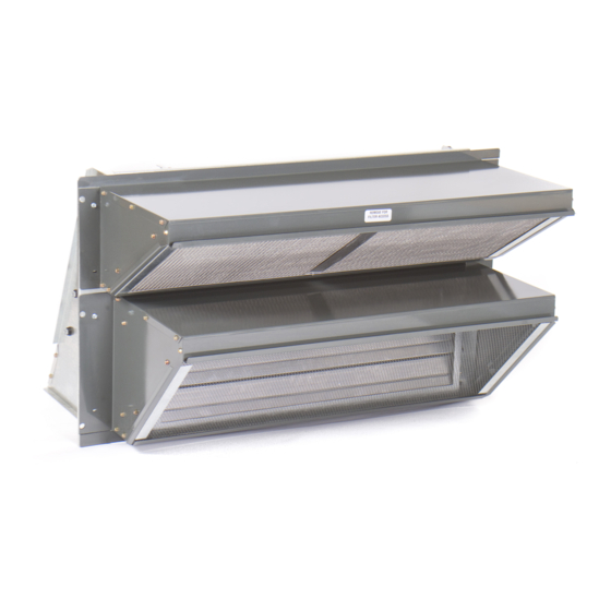
1 - Energy Recovery Wheel Assembly
1 - Outdoor Fresh Air Hood with Filter
1 - Outdoor Exhaust Hood with Filter
1 - Platform Support Rail
1 - Bag Assembly
- Gasketing.
- Foot pads
- Hardware for standoff legs.
- Wiring harness
- Hardware for attachment to economizer.
Package 2 of 2 contains:
1 - Balancing Damper Assembly
2 - Side Filler Panels
4 - Hat Sections
II - SHIP PING DAM AGE
Check unit for shipping damage. Receiving party should
contact last carrier immediately if shipping damage is
found.
III - GEN ERAL
These instructions are intended as a general guide and do
not supersede local codes in any way. Authorities having
jurisdiction should be consulted before installation.
IV - RE QUIRE MENTS
When installed, the unit must be electrically wired and
grounded in accordance with local codes or, in absence of
local codes, with the current National Electric Code,
ANSI/NFPA No. 70.
V - AP PLI CA TION
Energy Recovery Ventilators (ERV) are used with units
equipped with a return damper assembly. These wheels
conserve energy by mixing warmer air with cooler air in the
following manner:
Re cov ery Mode
The Re cov ery Mode is ac com plished by two blow ers
pro vid ing con tin u ous ex haust of stale in door air and
re place ment by equal amount of out door air. En ergy
re cov ery is achieved by slowly ro tat ing the En ergy
Re cov ery Wheel (ERW) within the cas sette frame work. In
win ter, the ERW ad sorbs heat and mois ture from the
ex haust air stream dur ing one half of a com plete ro ta tion
and gives them back to the cold, drier in take air sup ply
Energy recovery COMPONENT
certified to the AHRI Air-to-Air
E n e r g y R e co ve r y V e n t i l at i o n
Equipment Certification Program in
accordance with AHRI Standard
1060-2000. Actual performance in
packaged equipment may vary.
PAGE 1
INSTALLATION INSTRUCTIONS
dur ing the other half ro ta tion. In sum mer, the pro cess is
au to mat i cally re versed. Heat and mois ture are ab sorbed
from in com ing fresh air sup ply and trans ferred to the
ex haust air stream. This pro cess al lows out door air
ven ti la tion rates to be in creased by fac tors of three or more
with out ad di tional en ergy pen alty or increase in size of
heating or air conditioning systems.
VI - RIG GING UNIT FOR LIFT ING
1. Maximum weight of unit is — 600 Lbs. (Crated)
2. Remove crating. Then remove access panel (See
Figure 1) to retrieve bag assembly. Replace access
panel.
3. All panels must be in place for rigging.
4. Lifting lugs are supplied with the unit. Loosen machine
bolts and rotate lifting lug as shown in Figure 1.
LIFTING LUGS (4)
VII - IN STAL LA TION
1. Disconnect all power to rooftop unit.
R46A-11TDW
MAY 2, 2005
SUPERCEDES 11-14-02
ETL Certified per UL 1995
and CSA 22.2
ACCESS PANEL
Figure 1
Advertisement
Table of Contents

Related Manuals for Ruskin RRS Systems YCD


Summary of Contents for Ruskin RRS Systems YCD
- Page 1 INSTALLATION INSTRUCTIONS R46A-11TDW MAY 2, 2005 SUPERCEDES 11-14-02 EN ERGY RE COV ERY WHEEL INSTALLATION INSTRUCTIONS FOR ENERGY RECOVERY VENTILATOR (FIXED) USED WITH TRANE ROOFTOP UNIT MODELS YCD/TCD 15 TO 25 TON UNITS Energy recovery COMPONENT certified to the AHRI Air-to-Air E n e r g y R e co ve r y V e n t i l at i o n ETL Certified per UL 1995 Equipment Certification Program in...
-
Page 2: Operation
WARNING Electric shock hazard. Can cause injury or death. Before attempting to perform any service or maintenance, turn the electrical pow er to unit OFF at disconnect switch(es). Unit may have multiple power supplies. 2. Remove the rooftop unit horizontal return air access panels. -
Page 3: System Check
consists of a unique rotary energy recovery wheel that Re cov ery Mode rotates in and out of fresh air streams within a heavy duty, On a thermostat call for blower operation in heating, permanently installed blower cabinet that provides ready cooling or continuous blower, the ERW will rotate between access to all internal components. -
Page 4: Maintenance
3. Set thermostat to normal operating position. 4. Restore power to unit. X - MAIN TE NANCE Motor Maintenance All motors use prelubricated sealed bearings; no further lubrication is necessary. Mechanical Inspection Make visual inspection of dampers, linkage assemblies and ERV rotating bearings during routine maintenance. Filters should be checked periodically and cleaned when necessary. - Page 5 ENERGY RECOVERY VENTILATOR SCFM vs. PRESSURE DROP R46 Series 1000 RP M 900 RP M 800 RP M 1.60 1.50 1.50 1.49 1.49 1.46 1.44 1.41 1.40 1.38 1.35 1.29 1.25 1.20 1.20 1.20 1.19 1.18 1.18 1.16 1.13 1.10 1.10 1.10 1.05...
- Page 6 ERV UNIT SCHE MATIC DIAGRAM COM PO NENT CODE A131 Fixed Re lay Board Mo tor, Ex haust Air Mo tor, Fresh Air Mo tor, Des ic cant Wheel Mo tor, Damper (Op tional) Ca paci tor, Wheel Mo tor DL43 De lay, Cy cle Timer (Op tional) Fuse...
- Page 7 ERV UNIT WIR ING DIAGRAM Notes: Remove jumper to install field optional low ambient switch. Step-down transformer assembly for 460 volt units. Selective voltage terminal for proper unit voltage Optional low ambient switch. Optional motorized intake damper. Des ic cant Wheel for Roof top Unit Optional stop, start and jog control.
Need help?
Do you have a question about the RRS Systems YCD and is the answer not in the manual?
Questions and answers