Advertisement
Quick Links
MiniCORE
INSTALLATION INSTRUCTIONS FOR MINICORE VENTILATOR (MCV) WITH FACTORY
INSTALLED OPTIONS USED AS A STAND ALONE OR WITH SPLIT SYSTEMS UNITS
I - Shipping And Packing List
Package 1 of 1 contains:
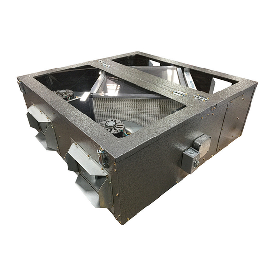
1 - MiniCore Ventilator Assembly
II - Shipping Damage
Check unit for shipping damage. Receiving party should
contact last carrier immediately if shipping damage is
found.
III - General
These instructions are intended as a general guide and
do not supersede local codes in any way. Authorities
having jurisdiction should be consulted before installation.
IV - Requirements
When installed, the unit must be electrically wired and
grounded in accordance with local codes or, in the
absence of local codes, with the current National Electric
Code, ANSI/NFPA No. 70.
V - Application
MiniCore ventilators are used as a stand alone indoor
option for heat recovery ventilators used in light
commercial applications. These ventilators conserve
energy by transferring heat energy across two opposing
air streams using a polymer core heat exchanger. This
process works in the summer by rejecting the heat energy
from incoming intake air and in the winter by conserving
the heat energy from the exhaust air, allowing outdoor
ventilation rates to be increased by factors of three or
more without additional energy penalty or increase in size
of the heating or air conditioning systems.
VI - Rigging Unit For Lifting
1. Maximum weight of unit is:
Model#
Net Weight
Ship Weight
2. Remove carton.
3. All panels must be in place for rigging.
4. Lift unit into place with a winch or jack.
Ventilator
ENERGY RECOVERY CORE
Energy recovery COMPONENT certified
to the AHRI Air-to-Air Energy Recovery
Ventilation
Program in accordance with AHRI Standard
1060-2000. Actual performance in packaged
equipment may vary.
MCV-500
MCV-1000
182
222
230
270
INSTALLATION INSTRUCTIONS
Equipment
Certification
Danger of sharp metallic edges. Can cause injury. Take care
when servicing unit to avoid accidental contact with sharp
VII - Installation
When choosing a location to mount the MiniCore
Ventilator take into consideration ductwork layout as well
as access for future filter changes and Core cleaning. See
maintenance section on Page 4 for dimensions.
Normal installation of the MiniCore Ventilator unit is
hanging from the 4 corners using the included hanging
kit though the units can be mounted on a shelf or on the
floor of a mechanical room using optional floor vibration
isolators.
CAUTION
edges.
WARNING
Electric shock hazard. Can cause injury or death.
Before attempting to perform any service or
maintenance, turn the electrical power to unit
OFF at disconnect switch(es). Unit may have
multiple power supplies.
Figure 1
MC500-1ERV
JANUARY 10, 2018
SUPERSEDES: NONE
ETL Certified
per UL 1995 and
CSA 22.2
1
Advertisement

Related Manuals for Ruskin MiniCORE MCV-500


Summary of Contents for Ruskin MiniCORE MCV-500
- Page 1 INSTALLATION INSTRUCTIONS Ventilator MiniCORE MC500-1ERV JANUARY 10, 2018 SUPERSEDES: NONE ENERGY RECOVERY CORE INSTALLATION INSTRUCTIONS FOR MINICORE VENTILATOR (MCV) WITH FACTORY INSTALLED OPTIONS USED AS A STAND ALONE OR WITH SPLIT SYSTEMS UNITS Energy recovery COMPONENT certified to the AHRI Air-to-Air Energy Recovery Ventilation Equipment Certification...
- Page 2 The maximum weight of a MiniCore Ventilator is less than High voltage: 225 lbs, Using 3/8" all-thread and the included hanging 115V: Connect the high voltage wires to L1 (Hot) & brackets is the preferable method of supporting the unit L2 (Common), hook the ground wire to the provided though the use of metal strap to hang the unit is also grounding nut.
- Page 3 B - Air Balancing Adjustment 1. Remove plastic plugs in access panels (4 total). 2. With a manometer measure pressure drop [inches of water column] diagonally across the MiniCore. Unit CFM for 3 speed PMC motors is determined then by referring to Table #1 on Page 5.
- Page 4 A - Core Removal (See Figure 5) B - Filter Removal (See Figure 6) 1. Remove Access panels by opening each panel and 1. Open the Filter Access panel by opening the two then releasing the spring loaded pins in the hinges by spring loaded latches to expose filters.
- Page 5 Blower Data for PSC Motors MCV 500 Cabinet External Static Pressure Medium High MCV1000 Cabinet External Static Pressure 1146 1124 1079 1042 1006 Medium 1388 1361 1307 1262 1218 1174 1084 1112 1080 1033 1001 High 1618 1586 1524 1471 1420 1368 1264...
- Page 6 MC500-1ERV...
- Page 7 MC500-1ERV...
- Page 8 START UP INFORMATION SHEET VOLTAGE - MCV UNIT Incoming Voltage L1-L2 Running Voltage L1-L2 Secondary Voltage AMPERAGE - MCV MOTORS Intake Motor: Nominal HP Rated Amps Running Amps Exhaust Motor: Nominal HP Rated Amps Running Amps Wheel Motor: Nominal HP Rated Amps Running Amps AIRFLOW...
Need help?
Do you have a question about the MiniCORE MCV-500 and is the answer not in the manual?
Questions and answers