Chroma Color Block PSU30 User Manual
Hide thumbs
Also See for Color Block PSU30:
- User manual (16 pages) ,
- User manual (11 pages) ,
- Quick start manual (2 pages)
Table of Contents
Advertisement
Quick Links
Advertisement
Table of Contents

Related Manuals for Chroma Color Block PSU30


Summary of Contents for Chroma Color Block PSU30
- Page 1 Chroma-Q™ Color Block™ PSU30 User Manual Version 1.2 December 2006 PN: 602-0503...
- Page 2 Suggestions of use shall not be taken as inducements to infringe any patent. Chroma-Q sole warranty is that the product will meet the sales specifications in effect at the time of shipment. Your exclusive remedy for breach of such warranty is limited to refund of purchase price or replacement of any product shown to be other than as warranted.
-
Page 3: Table Of Contents
Table of Contents Product Overview ……………………..………………………….………....3 Operation ……………...…………………………………………………….………… 3 Cabling …………………………………………………………………………… 3 Control ………………………………………………………………………… 5 Control menu ……………………………………………………………… 5 DMX personality mode 1-3 ……………………………………………… 7 DMX personality mode 4-6 ……………………………………………… 8 DMX personality mode 7-9 ………………………………………….… 9 Technical Information ………………………………………………………. 10 Specification ……………………………………………………………... -
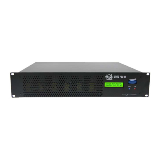
Page 4: Product Overview
Product overview The Color Block PSU-30 is a 2U 19” rack mounted power supply suitable for up to 30 Color Block DB4 LED fixtures. It can be controlled remotely via ANSI E1.11 USITT DMX 512-A in a variety of modes to accommodate most applications or can operate independently as a standalone system. - Page 5 Note: Due to the higher levels of leakage current of the PSU-30 it is important that the XLR4 cables used are manufactured only to the specification detailed above. It is also important that the cables are not coupled or uncoupled whilst the PSU is powered and that the PSU is correctly grounded.
-
Page 6: Control
2.2 Control The Color Block PSU-30 menu items are accessed via the LCD display and the following controls: • Right hand button (red) = Enter (hold for 2 seconds to save) • Left hand button (blue) = Exit without saving •... - Page 7 engine to create the desired effect. Scroll to Look Store and press Enter, scroll to desired Look and press Enter. Press Enter again for 2 seconds to save Look. Advanced, standalone. Set the PSU-30 to Control Mode 1. Scroll to Look Store and press Enter, scroll to desired Look and press Enter to access the memory data.
-
Page 8: Dmx Personality Mode 1-3
b. DMX personality mode 1-3 In modes 1-3 each cell is a group PSU-30 (v1.0) Mode 1 (367ch) Mode 2 (360ch) Mode 3 (360ch) 120 x HSI + FX 120 x HSI 120 x RGB Channel 1 Grouping Hue for group 1 Red for group 1 0-100 Variable grouping range between 1-120 cells with FX... -
Page 9: Dmx Personality Mode 4-6
c. DMX personality mode 4-6 In modes 4-6 each Color Block DB4 fixture (4 cells) is a group PSU-30 (v1.0) Mode 4 (96ch) Mode 5 (90ch) Mode 6 (90ch) 30 x HSI + FX 30 x HSI 30 x RGB Channel 1 Colour Speed Hue for group 1... -
Page 10: Dmx Personality Mode 7-9
d. DMX personality mode 7-9 In modes 7-9 all PSU-05 output is grouped as one PSU-30 (v1.0) Mode 7 (9ch) Mode 8 (3ch) Mode 9 (3ch) HSI + FX Channel 1 Colour Speed Hue for group 1 Red for group 1 0-255 Variable speed of colour scrolling. -
Page 11: Technical Information
Technical information a. Specifications Product code: CHCBPSU30 (max 30 DB4s) Dimensions: 483mm × 368mm × 89mm 19" × 14.5" × 3.5" Weight: 11.1kg / 24.5lbs Working Voltage: 100-240VAC 50/60Hz auto-switching Power consumption: 18A @120VAC; 9A @ 240VAC Output connector in/out: XLR4 Sync: Ethercon RJ45 in and through... -
Page 12: Installation
d. Installation The Color Block PSU-30 must be installed in a 2U rack mounted enclosure and be supported front and rear. Ensure adequate ventilation around the front and rear of the enclosure. Failure to allow adequate ventilation may result in premature failure of the unit. e.
Need help?
Do you have a question about the Color Block PSU30 and is the answer not in the manual?
Questions and answers