Advertisement
Quick Links
Morel Ardon Bookshelf Speaker Kit
Thank you for purchasing the More Ardon bookshelf speaker kit. This speaker kit was precision
cut using CNC machinery for the best possible fit and finish. With a little time and patience, your
finished product will provide years of enjoyment. Please follow the following instructions for the
best possible results.
Suggested tools and consumables:
Drill
5/64" drill bit
Wood clamps (you can never have too many of these)
Sanding block and/or electric finishing sander
Wood glue
0.11" female disconnect terminal
0.205" female disconnect terminal
Package contents:
First, empty the contents of the package and review parts to ensure everything has been included
and is in good condition. If any parts are missing or damaged please contact our customer service
department at 1-800-338-0531.
Note: Crossover components may be substituted with parts of equal of higher quality depending
on stock.
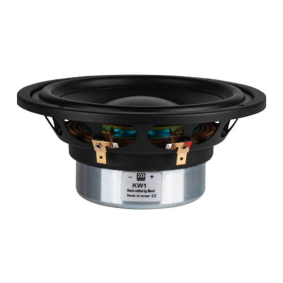
A) Morel KW-1 6" Damped Poly Cone Woofer
B) Morel KT-1 1-1/8" Neodymium Soft Dome Tweeter
C) 2" ID Adjustable Port Tube
Rag or paper towels
Solder
Soldering iron
Hot glue gun
Polyurethane glue (Gorilla Glue)
Cyanoacrylate Adhesive (super glue)
Components:
Advertisement

Subscribe to Our Youtube Channel
Related Manuals for Morel Ardon


Summary of Contents for Morel Ardon
- Page 1 Morel Ardon Bookshelf Speaker Kit Thank you for purchasing the More Ardon bookshelf speaker kit. This speaker kit was precision cut using CNC machinery for the best possible fit and finish. With a little time and patience, your finished product will provide years of enjoyment. Please follow the following instructions for the best possible results.
- Page 2 D) Dayton Audio BPA-38G HD Binding Post Pair Gold E) White Perforated Large Hole Crossover Board 3.5" x 5" F) 16 AWG 2-conductor Power Speaker Wire 4 ft. (Red/Black) G) 25-Pack #6 x 3/4" Pan Head Deep Thread Black Screws H) Dayton Audio LW141 1.0mH 14 AWG Perfect Layer Inductor I) Dayton Audio AC20-40 0.40mH 20 AWG Air Core Inductor Coil J) Dayton Audio PMPC-12 12uF 250V Precision Audio Capacitor...
-
Page 3: Enclosure Assembly
Enclosure Assembly: 1) First, before gluing anything, do a dry fit of the enclosure to familiarize yourself with the parts and assembly. This will also give you a chance to ensure that all pieces have been cut properly. 2) Due the design of this enclosure, it can easily be assembled in one sitting, using as little as 6 clamps. - Page 4 With one Side Panel laying flat, glue all mating surfaces of the dado in the Side Panel and one side of the Brace Assembly. Insert the Brace Assembly as shown. Make sure the Brace Assembly is seated completely in the dado. Glue all mating surfaces of Bottom Panel, Side Panel, and Brace Assembly.
- Page 5 Glue all mating surfaces of the Back Panel, Bottom Panel, Side Panel, and Brace Assembly. Insert the Back Panel as shown. Make sure the Brace Assembly posts are seated completely in the matching notches on the Back Panel. Note: Make sure the port cutout is lined up with the notch at the top of the brace assembly. Glue all mating surfaces of Top Panel, Side Panel, Back Panel, and Brace Assembly.
- Page 6 Glue all mating surfaces of the second Side Panel, Top Panel, Bottom Panel, and Brace Assembly. Insert the second Side Panel as shown. Make sure the Brace Assembly is seated completely in the dado on the second Side Panel. 10) Glue all mating surfaces of the Front Panel, Bottom Panel, Side Panels, and Brace Assembly.
- Page 7 11) Make sure that all edges are flush and securely apply clamps from side to side, top to bottom, and front to back. Apply ample pressure to ensure glue is spread evenly through each joint (some glue squeeze-out can be expected). Visually inspect all seams to make sure they are all closed tightly, you may need to relocate clamps (or add more clamps) to get a perfect fit.
-
Page 8: Crossover Assembly
Crossover assembly: Point-to-point wiring diagram 14) Arrange the components on the White Perforated Crossover Board as illustrated in the point- to-point wiring diagram above so the leads can be connected together as shown on the back side of the board. Take careful note of the component type and the value of the component. (The crossover schematic is provided at the end of this assembly guide.) 15) Connect the leads of the components as shown in the diagram by twisting them together or creating interlocking "hooks"... - Page 9 16) With a hot soldering iron, apply solder to the connections between components. Heat the junctions evenly and verify that the solder flows into the connections rather than forming a "blob" on the surface (cold joint). 17) Cut two lengths of 2-conductor speaker wire approximately 14"-16" in length, then solder them at the outputs of the crossover network labeled "woofer"...
-
Page 10: Final Assembly
Using a screwdriver, secure woofer using the included #6 x 3/4" Pan Head screws, just until tight, being careful not to strip out the holes (a power drill is not recommended). 25) You are now ready to enjoy your finished Morel Ardon bookshelf speaker. - Page 11 Morel Ardon Crossover Schematic: Morel Ardon Frequency Response 1M/2.83V...
Need help?
Do you have a question about the Ardon and is the answer not in the manual?
Questions and answers