
Related Manuals for Magnetic MHTM FlowMotion mTripod


Summary of Contents for Magnetic MHTM FlowMotion mTripod
- Page 1 Operating Instructions Turnstile MHTM™ FlowMotion® mTripod Doc. ID: 5817,0026EN Version 02 58170026EN_02.indd 1 04.04.2019 16:08:57...
- Page 2 MAGNETIC AUTOCONTROL GMBH Grienmatt 20 D-79650 Schopfheim Germany Phone +49 7622 695 5 Fax +49 7622 695 802 info@magnetic-germany.com www.magnetic-access.com...
-
Page 3: Table Of Contents
mTripod Contents Contents Notes on the document Purpose and contents of this operating instructions Read and store the operating instructions Non-compliance with the operating instructions Symbols and illustrations used in these operating instructions 1.4.1 Warning notes and notes Safety Intended use Changes and modifications Target groups 2.3.1... - Page 4 mTripod Contents Receipt of goods, transport and storage Goods receiving department Safety during transport Transport Storage Unpacking, scope of delivery and identification Unpacking Scope of delivery Identification 6.3.1 Type plate Installation and assembly Safety during installation and assembly Mounting options Required steps Setting up foundation and placing empty conduits 7.4.1...
- Page 5 mTripod Contents Electrical connection Safety during electrical connection Installing electrical protective devices Connecting the mains cable Connecting customer control lines 8.4.1 Connecting emergency opening contacts Installing and connecting customer-access control devices Checking the electrical connections Commissioning Safety during commissioning Putting the pedestrian gate into operation Switching the pedestrian gate on and off Parameterising the pedestrian gate Test book...
- Page 6 mTripod...
-
Page 7: Notes On The Document
mTripod Notes on the document Notes on the document Purpose and contents of this operating instructions These operating instructions provide all the information required for the product in the various phases of its life cycle. These operating instructions contains the following information: Assembly and function, transport and storage, unpacking and delivery, installation and assembly, electrical connection, commissioning, operation, cleaning and maintenance, decommissioning, dismantling and disposal. -
Page 8: Non-Compliance With The Operating Instructions
Notes on the document Non-compliance with the operating instructions Magnetic declines all liability for personal injury and material damage caused by not observing the operating instructions. This applies in particular to damage caused by: › Non-intended use › Use of non-qualified personnel ›... - Page 9 mTripod Notes on the document CAUTION The signal word CAUTION points to a potentially dangerous situation, which can lead to minor injuries if it is not avoided. NOTICE The signal word NOTICE points to a potentially harmful situation, which leads to property damage if it is not avoided. Notes and recommendations IMPORTANT! The signal word IMPORTANT highlights useful notes and...
-
Page 10: Safety
The turnstile may only be operated within the temperature range indicated on the type plate. Misapplications Any other or further use is considered improper use. Magnetic is not liable for any resulting personal injury or damage to property. For example, the following applications are considered to be contrary to regulations: ›... -
Page 11: Target Groups
mTripod Safety Target groups 2.3.1 Operator and his responsibilities The operator must comply with the statutory obligations regarding work safety. In addition to the safety instructions and warning notes in these operating instructions, the valid safety, accident prevention and environmental protection regulations must be observed. -
Page 12: Personnel - Activities And Qualifications
Can assess the work assigned to her/him, recognises possible dangers and take suitable safety measures. › Magnetic MHTM™ FlowMotion® Meets all requirements of the technician. › service expert Trained and authorised by Magnetic. › Operator Trained by the operator. Table 1: Qualifications of personnel... -
Page 13: Personal Protective Equipment
Safety Action Transport Technician Magnetic Operator equipment service expert operator Transporting – – Unpacking – Laying the foundation – – – Assembly – – Electrically connect – – Parameterise – – Commissioning – – Operating – Cleaning – Waiting –... -
Page 14: Symbols On The Device
mTripod Safety Symbols on the device Warning of dangerous electrical voltage! The warning sign indicates hazardous areas with dangerous electrical voltage. Non-observance of the warning signs causes severe injuries or death. The work to be carried out may only be carried out by a qualified electrician or an electric safety expert. -
Page 15: For Your Safety
mTripod Safety For your safety Mortal danger by electric voltage! Touching live parts can be lethal. Damaged insulation or damaged parts may be fatal. › If the insulation or any parts are damaged, switch off the power supply at once and initiate repair. ›... -
Page 16: To Protect The Environment
mTripod Safety To protect the environment Improper disposal! Improper disposal can lead to damage to the environment. › Dispose of product in accordance with local and national laws and regulations. › Sort resources and supply them to recycling. Emergency opening of the pedestrian gate ä... -
Page 17: Technical Data
mTripod Technical data Technical data Dimensions and design 3.1.1 mTripod-ML 1300 1239.5 Fig. 1: Dimensions FMTP-ML (dimensions in mm) Dimensions for customer's access-control device... - Page 18 mTripod Technical data Designation Value Dimensions 1300 mm x 290 mm x 1050 mm (length x width x height) ä Page 17, Fig. 1. Passage width 515 mm › Weight Turnstile complete: Approx. 70 kg › Optional foundation frame: Approx. 10.5 kg ›...
-
Page 19: Mtripod-Ms
mTripod Technical data 3.1.2 mTripod-MS Fig. 2: Dimensions FMTP-MS (dimensions in mm) Dimensions for customer's access-control device Designation Value Dimensions 730 mm x 290 mm x 1050 mm (length x width x height) ä Page 19, Fig. 2. Passage width 515 mm ›... -
Page 20: Clearances And Line Configuration To Be Maintained
mTripod Technical data Clearances and line configuration to be maintained Mag00817a Fig. 3: Clearances and line configuration to be maintained Minimum distance 50 mm... -
Page 21: Electrical Connection
mTripod Technical data Electrical connection Designation Value Power supply 100 to 240 V AC ± 10 %, 50 to 60 Hz Current consumption at 240 V AC 1.0 A Current consumption at 100 V AC 2.1 A Max. power 174 W Duty cycle 100 % Table 5:... -
Page 22: Control Unit Mgc
mTripod Technical data Control unit MGC Designation Value Power supply 24 V DC Control unit max. 1 A max. 300 mA + current consumption of the different plug-in modules Power consumption max. 24 W: Max. 7.2 W + Power consumption of the individual plug-in modules Control unit safety 1 A T... -
Page 23: Design And Function
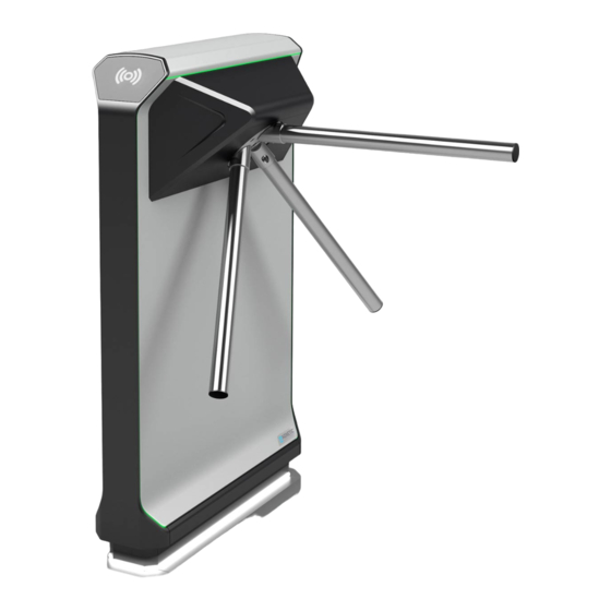
mTripod Design and function Design and function Design Fig. 4: Design, shown here mTripod FMTP-ML Room for access-control device provided by the customer, e.g. card reader Space for GED (passage direction display) Control unit MGC Drive for blocking element, consisting of 3 blocking arms Blocking arm (3 x) Cover for control unit and drive blocking element consisting of cover and trapezoidal plate... -
Page 24: Function
Furthermore, the turnstile can be used in free entry or exit mode. For emergencies such as fire or power failures Magnetic has developed the option "drop arm". With this option, when an emergency is triggered or in the event of a power failure, the blocking arm, which is at the top at this time, unlocks. -
Page 25: Receipt Of Goods, Transport And Storage
Safety during transport Qualification of personnel › Transport equipment operator › Technician › Magnetic MHTM™ FlowMotion® service expert ä Page 12, chapter 2.3.2. Personal protective equipment Wear the following personal protective equipment: › Work clothes › Protective gloves ›... -
Page 26: Transport
mTripod Receipt of goods, transport and storage WARNING Lifting of heavy loads! The weight of heavy objects can severely injure a person's back or supportive system. › Preferably transport the transported goods with suitable transport aids. › Alternatively, the transported goods can be carried by two persons. -
Page 27: Storage
mTripod Receipt of goods, transport and storage Storage Store packages or the product under the following conditions: › Store the delivery in its original packaging. Observe the symbols on the packaging. › Do not store outdoors. › Store dry and dust free. ›... -
Page 28: Unpacking, Scope Of Delivery And Identification
Unpack product at final location. Place the product vertically. Report incomplete and faulty delivery to Magnetic. Check the scope of delivery with the delivery note. Separate material according to type and size and continue to use them... -
Page 29: Scope Of Delivery
mTripod Unpacking, scope of delivery and identification Scope of delivery The following components are supplied as standard for each mTripod turnstile: › 1 mTripod turnstile with mounted rear panel and trapezoidal plate › Front panel › Cover › 3 blocking arms ›... -
Page 30: Identification
Unpacking, scope of delivery and identification Identification 6.3.1 Type plate The type plate is located under the cover to the right of the drive unit. MAGNETIC AUTOCONTROL GmbH D-79650 Schopfheim Ser.-Nr. Made in Germany Fig. 5: Type plate Product name... -
Page 31: Installation And Assembly
Installation and assembly Installation and assembly Safety during installation and assembly Qualification of personnel › Technician › Magnetic MHTM™ FlowMotion® service expert ä Page 12, chapter 2.3.2. Personal protective equipment Wear the following personal protective equipment: › Work clothes ›... -
Page 32: Mounting Options
mTripod Installation and assembly Mounting options You can install the mTripod turnstile as follows: Mounting variant Material required per turnstile Comments (attachments) › Mount the turnstile directly on Attachment set BSS100 for Use M8 x 30 screws. Do not use a foundation. -
Page 33: Setting Up Foundation And Placing Empty Conduits
mTripod Installation and assembly Setting up foundation and placing empty conduits 7.4.1 Requirements foundation The foundation must meet the following requirements: › Have sufficient load-carrying capacity › Concrete C20/25 or corresponding industrial floor › Attachment must be able to grip securely ›... -
Page 34: Setting Up Foundation And Placing Empty Conduits
mTripod Installation and assembly 7.4.3 Setting up foundation and placing empty conduits Excavate the foundation hole according to the foundation and empty conduit plan. ä Page 35, Fig. 6. ä Page 36, Fig. 7. If installed outdoors, lay the reinforcement braid. Place empty conduits according to the foundation and empty conduit plan in the foundation hole. -
Page 35: Foundation And Empty Conduit Plan And Reinforcement Mtripod Fmtp-Ml
mTripod Installation and assembly 7.4.4 Foundation and empty conduit plan and reinforcement mTripod FMTP-ML (180) 22.5 Fig. 6: mTripod FMTP-ML foundation and empty conduit plan (dimensions in mm) Foundation, frost depth, outdoor area Outline mTripod FMTP-ML Boreholes (8 x) Feed-through for empty conduits Passage side, side of the locking arms... - Page 36 mTripod Installation and assembly ∅ 8 ∅ 8 Fig. 7: Reinforcement plan FMTP-ML (dimensions in mm)
-
Page 37: Foundation And Empty Conduit Plan And Reinforcement Mtripod Fmtp-Ms
mTripod Installation and assembly 7.4.5 Foundation and empty conduit plan and reinforcement mTripod FMTP-MS (180) 22.5 Fig. 8: mTripod FMTP-MS foundation and empty conduit plan (dimensions in mm) Foundation, frost depth, outdoor area Outline mTripod FMTP-MS Boreholes (6 x) Feed-through for empty conduits Passage side, side of the locking arms... - Page 38 mTripod Installation and assembly ∅ 8 ∅ 8 Fig. 9: Reinforcement plan FMTP-ML (dimensions in mm)
-
Page 39: Base Plate And Drilling Template Mtripod Fmtp-Ml
mTripod Installation and assembly Base plate and drilling template mTripod FMTP-ML Note that, depending on the mounting variant, only 8 threaded rods or 8 screws are required for mounting the mTripod FMTP-ML turnstile. See following figure, positions 6 and 9. 1239.5 1150 Fig. -
Page 40: Base Plate And Drilling Template Mtripod Fmtp-Ms
mTripod Installation and assembly Base plate and drilling template mTripod FMTP-MS Note that, depending on the mounting variant, only 6 threaded rods or 6 screws are required for mounting the mTripod FMTP-MS turnstile. See following figure, position 8. 669.5 1150 Fig. -
Page 41: Aligning The Pedestrian Gate
mTripod Installation and assembly Aligning the pedestrian gate When installing several pedestrian gates, align the pedestrian gates to the customer's specifications and to the on-site conditions, e.g. walls, tile joints and railings, using a laser or scale. Assembly of the mTripod 7.8.1 Mounting variant “Direct mounting”... - Page 42 mTripod Installation and assembly Fig. 12: Mounting variant "Direct mounting" – mount turnstile, shown here mTripod FMTP-ML Drill hole (FMTP-ML: 8 x and FMTP-MS: 6 x) Female threaded sleeves 12 x 90, M8, stainless steel (FMTP-ML: 8 x and FMTP-MS: 6 x) Washer A 8.4 mm, stainless steel (4 x) Screw M8 x 30, stainless steel (FMTP-ML: 8 x and FMTP-MS: 6 x) U-profiles (4...
- Page 43 mTripod Installation and assembly IMPORTANT! Follow the separate notes and instructions for the composite mortar and foundation anchors. ä Foundation and empty conduit plan mTripod FMTP-ML: Page 35, Fig. 6. ä Foundation and empty conduit plan mTripod FMTP-MS: Page 37, Fig. 8. Drill the boreholes for the female threaded sleeves according to the foundation plan.
-
Page 44: Mounting Option "Mount Base Plate
mTripod Installation and assembly 7.8.2 Mounting option «Mount base plate» With this type of installation, first mount the base plate on the foundation or on the unfinished floor. After completion of the finished floor, install the turnstile on the finished floor using threaded rods. For the variant mTripod FMTP-ML you need 8 threaded rods. - Page 45 mTripod Installation and assembly Fig. 13: Mounting and preparing the base plate Foundation / raw floor Planned finished floor Drilling template Nut M8, slightly above the planned finished floor (FMTP-ML: 8 x and FMTP-MS: 6 x) Threaded rods M8 x 210, stainless steel (FMTP-ML: 8 x and FMTP-MS: 6 x) Nut M8 (FMTP-ML: 8 x and FMTP-MS: 6 x) Base plate...
- Page 46 mTripod Installation and assembly Mounting the turnstile after completion of the finished floor Prerequisites › The finished floor is finished. Remove the drilling template and nuts from the threaded rods. Fig. 14: Remove drilling template and nuts Flex off threaded rods 20 mm above the finished floor. Fig.
- Page 47 mTripod Installation and assembly Fig. 16: Mounting variant "Mount base plate" – Mount turnstile, shown here mTripod FMTP-ML Nut M8 (FMTP-ML: 8 x and FMTP-MS: 6 x) Washer A 8.4 mm, stainless steel (4 x) Threaded rods M8 x 210, stainless steel (FMTP-ML: 8 x and FMTP-MS: 6 x) U-profiles (4 x)
-
Page 48: Mounting Variant "Glue Base Plate
mTripod Installation and assembly 7.8.3 Mounting variant “Glue base plate” With this type of installation, you first glue the base plate onto the foundation or the finished floor. Then mount the turnstile on the base plate. For the variant mTripod FMTP-ML you need 8 screws. For the variant mTripod FMTP-MS you need 6 screws. - Page 49 mTripod Installation and assembly Place and align base plate. NOTICE Wrong orientation of the turnstile! The turnstile is not symmetrically constructed. Align the turnstile so that the passage side is on the correct side. Note figure base plate. Draw the outline of the base plate on the floor. Make sure that the markings are either washable or invisible.
- Page 50 mTripod Installation and assembly Immediately place the base plate on the adhesive. Observe markings. Fig. 19: Place base plate Press the base plate on well immediately. If the base plate stands out due to unevenness of the floor, weight the base plate. Remove excess adhesive as soon as possible with “Klebt + Dichtet Entferner”.
- Page 51 mTripod Installation and assembly Fig. 20: Mounting variant "Glue base plate" – Mount turnstile, shown here mTripod FMTP-ML Screw M8 x 16, stainless steel (FMTP-ML: 8 x and FMTP-MS: 6 x) Washer A 8.4 mm, stainless steel (4 x) Base plate U-profiles (4 x)
-
Page 52: Assembling Mtripod
mTripod Installation and assembly Assembling mTripod Prerequisites › The turnstile is mounted on the floor. The turnstile is delivered with assembled rear panel and assembled trapezoidal plate. Cover, front panel and blocking arms are not assembled on delivery. Fig. 21: Turnstile in delivery state Rear panel Trapezoidal plate... - Page 53 mTripod Installation and assembly Disassemble the holding bracket. To do this, loosen the 4 screws. Fig. 22: Disassembly of the holding bracket Disassemble the trapezoidal plate. To do this, loosen the 2 screws. Fig. 23: Disassemby of the trapezoidal plate...
- Page 54 mTripod Installation and assembly Arrange electrical connections. ä Page 62, chapter 8. Assemble the trapezoidal plate. Assemble the holding bracket. Assemble the front panel. A click sound is heard each time it clicks into place. click Fig. 24: Assembly of the front panel...
- Page 55 mTripod Installation and assembly Attach the front panel with the 4 screws. Fig. 25: Attachment of the front panel Assemble the cover. The cover is held by 2 magnets. CAUTION Danger of crushing! Hold the cover with both hands only on the side. Do not hold the cover at the front or top edge.
- Page 56 mTripod Installation and assembly Assemble blocking arms. › Blocking arms with drop arm function: ä Page 56, chapter Fig. 27 › Blocking arms without drop arm function: ä Page 57, chapter Fig. 28 IMPORTANT! The scope of delivery includes one attachment set for blocking arms without “drop arm”...
- Page 57 mTripod Installation and assembly Fig. 28: Assembly of the blocking arms without drop arm function Observe the assembly sequence of the washer, north lock washer and hexagon head screw.
-
Page 58: Dismantling And Mounting Cover
mTripod Installation and assembly 7.10 Dismantling and mounting cover For the following activities, for example, you must disassemble the cover: › Switch the pedestrian gate on and off. › Parameterise the control unit MGC. The cover is held by 2 magnets. Disassembling the cover Place the supplied tool near the magnets. - Page 59 mTripod Installation and assembly Mounting the cover Hang in the cover. CAUTION Danger of crushing! Hold the cover with both hands only on the side. Do not hold the cover at the front or top edge. Tilt the cover backwards until the magnets close the cover. Fig.
-
Page 60: Opening And Closing The Housing
mTripod Installation and assembly 7.11 Opening and closing the housing To perform the electrical connection you have to open the housing. Opening the housing Disassemble cover. ä Page 41, chapter 7.8. Disassemble blocking arms. ä Page 56, Fig. 27 or Page 57, Fig. 28 Loosen the 4 screws of the front panel. -
Page 61: Checking The Assembly
mTripod Installation and assembly Disassemble holding bracket. ä Page 53, Fig. 22. Disassemble trapezoidal plate. ä Page 53, Fig. 23. Closing the housing Assemble trapezoidal plate. Assemble holding bracket. Assemble front panel. Assemble blocking arms. Assemble cover. ä Page 41, chapter 7.8. 7.12 Checking the assembly After assembly, check the following points:... - Page 62 Electrical connection Electrical connection Safety during electrical connection Qualification of personnel › Technician › Magnetic MHTM™ FlowMotion® service expert ä Page 12, chapter 2.3.2. Personal protective equipment Wear the following personal protective equipment: › Work clothes › Protective gloves ›...
- Page 63 Protect yourself in buildings or vehicles. NOTICE Electromagnetic interference! The pedestrian gate is approved for industrial, residential, commercial and business use. Operation in other electro- magnetic environmental conditions may cause interference or malfunctions. › Place control lines and mains cables into separate conduits. ›...
- Page 64 mTripod Electrical connection Connecting the mains cable IMPORTANT! The wire cross-section of the mains cable must be between 1.5 and 4 mm². Observe national provisions on line length and associated line cross-section. Prerequisites › The housing is open. ä Page 60, chapter 7.11. Disconnect the system from the power supply.
- Page 65 mTripod Electrical connection Fig. 33: Placing and connecting the mains cable Feed-through for empty conduits and lines Straps for fixing empty conduits and lines Terminals Mains cable to be connected Connecting customer control lines IMPORTANT! For connecting the control lines provided by the customer, see separate document "Description of MGC control unit for mTripod (Doc.ID: 5817,0025)".
- Page 66 mTripod Electrical connection 8.4.1 Connecting emergency opening contacts ä Separate wiring diagram and document "Description control unit MGC for mTripod (Doc.ID: 5817,0025)". Connect fire service switches, emergency opening contacts, etc. to the "Emergency release" input. This input has the highest priority. The "Emergency open"...
- Page 67 mTripod Electrical connection On the rear panel of the turnstile In general, you can also mount devices on the rear panel of the turnstile. The maximum permitted drilling depth is 5 mm. Additional mTripod FMTP-MS: The rear panel of the mTripod FMTP-MS turnstile is additionally equipped with struts.
- Page 68 mTripod Electrical connection Checking the electrical connections After the electrical installation, check the following points: › Does the power supply match the specification on the type plate? › Are the prescribed protective devices installed? › Is the pedestrian gate connected according to wiring diagram? ›...
- Page 69 Commissioning Commissioning Safety during commissioning Qualification of personnel › Technician › Magnetic MHTM™ FlowMotion® service expert ä Page 12, chapter 2.3.2. Personal protective equipment Wear the following personal protective equipment: › Work clothes › Protective gloves › Safety shoes.
- Page 70 mTripod Commissioning Disassemble cover. ä Page 41, chapter 7.8. Switch the pedestrian gate on or off using the on/off switch. Fig. 36: Switching the mTripod on and off On and off switch Assemble cover.
- Page 71 mTripod Test book Parameterising the pedestrian gate IMPORTANT! For parameterisation see separate document "Description of MGC control unit for mTripod (Doc.ID: 5817,0025)". Test book The pedestrian gate must be checked at least once a year in accordance with the test book. The test book "MHTM FlowMotion®...
- Page 72 mTripod Operation Operation The operation of the pedestrian gate depends on the connected access-control devices, signal transmitters and signal receivers as well as on the parameterisation of the control unit. We recommend to create a description for the operation, depending on the connected devices and the parameterisation.
- Page 73 mTripod Corrective action 12.2 Maintenance schedule The maintenance plan lists all work required to ensure safe, optimum and trouble-free operation of the pedestrian gate. Interval Work Personnel Monthly Check emergency function. Operator Check the “drop arm” function for turnstiles Operator with the “drop arm”...
- Page 74 mTripod Spare parts and repair Spare parts and repair NOTICE Wrong and faulty spare parts! Incorrect or defective spare parts can result in damage, malfunctions or total failure and also impair safety. › Use only the manufacturer's original spare parts. Spare parts are available from your authorised dealer.
- Page 75 ä Page 69, chapter 9.3. 16.1 Safety during decommissioning Qualification of personnel › Technician › Magnetic MHTM™ FlowMotion® service expert ä Page 12, chapter 2.3.2. Personal protective equipment Wear the following personal protective equipment: › Work clothes › Protective gloves ›...
- Page 76 17.1 Safety during disassembly and disposal Qualification of personnel › Technician › Electrical specialist › Magnetic MHTM™ FlowMotion® service expert ä Page 12, chapter 2.3.2. Personal protective equipment Wear the following personal protective equipment: › Work clothes › Protective gloves ›...
- Page 77 EU-Declaration of Conformity The manufacturer MAGNETIC AUTOCONTROL GmbH hereby declares for the product supplied by him: Designation Pedestrian gate FlowMotion® Type mTripod FMTP-M* From serial number F10044260 The conformity according to: Directive 2006/42/EC (Machine directive) amended by 2009/127/EC Directive 2014/30/EU (EMC directive)
- Page 78 mTripod...
- Page 79 FMTP-MS ....... 37 Dimensions ..........17 Line configuration ........20 mTripod-ML ......... 17 mTripod-MS ......... 19 Disassembly ..........76 Magnetic MHTM™ FlowMotion® service Top cover ..........58 expert ............12 Disposal ........... 76 Mains cable Connecting ........... 64 Maintenance schedule ......73...
- Page 80 mTripod Index Misapplications ........10 Technical data .......... 17 Modifications........... 10 Test book ..........71 Mounting options ........32 Top cover Direct mounting ........41 Assembly ..........59 Glueing the base plate ......48 Disassemble ......... 58 Mounting the base plate ..... 44 Transport ..........
- Page 81 mTripod...
- Page 82 mTripod...
- Page 83 mTripod...
- Page 84 MAGNETIC AUTOCONTROL GMBH Sales partner Grienmatt 20 D-79650 Schopfheim Germany Phone +49 7622 695 5 Fax +49 7622 695 802 info@magnetic-germany.com www.magnetic-access.com F10044441 58170026EN_02.indd 84 04.04.2019 16:09:16...
Need help?
Do you have a question about the MHTM FlowMotion mTripod and is the answer not in the manual?
Questions and answers