
Related Manuals for Baumer hhs ULT 400 XL


Summary of Contents for Baumer hhs ULT 400 XL
- Page 1 Operation manual ULT 400 XL Sensor: Adhesive monitoring Read this manual prior to performing any task! Translation of the original German document, dated 5/3/2021 English...
- Page 2 Baumer hhs GmbH Adolf-Dembach-Straße 19 47829 Krefeld Germany Telephone: +49 2151 4402 200 Fax: +49 2151 4402 111 E-mail: service.de@baumerhhs.com Internet: www.baumerhhs.com Translation of the original operation manual 79015692, 1, en_US © Baumer hhs GmbH 2021 ULT 400 XL 04.05.2021...
- Page 3 Supplemental directives Information on the operating This manual is an integral part of the Baumer hhs product and manual must be kept within close proximity of the system for personnel to access at all times. This manual enables the device to be handled safely and efficiently.
- Page 4 Copyright protection Baumer hhs GmbH operating manuals and handbooks are pro- tected by copyright. The copying, reproduction and translation, etc. of them is prohibited. Additional copies of this operating manual and copies in other languages can be obtained directly from Baumer hhs.
- Page 5 Supplemental directives Reporting hazards Email: hazardous@baumerhhs.com Documentation Email: dokumentation@baumerhhs.com 04.05.2021 ULT 400 XL...
-
Page 6: Table Of Contents
2.15 Safety guidelines for maintenance and resolving faults................. 23 2.16 Safety information for replacement parts....24 2.17 Component-specific safety guidelines and residual risks of the Baumer hhs system........ 24 2.17.1 Sensor ULT 400 XL..........24 Layout and functional description........26 3.1 Function..............26 3.1.1 Sensor ULT 400 XL.......... - Page 7 Table of contents 6.2.1 Sensor ULT 400 XL..........35 Operation................37 7.1 Operation ULT 400 XL..........37 7.1.1 Sensor ULT 400 XL..........37 Maintenance..............41 8.1 Maintenance table............41 8.2 Maintenance work ULT 400 XL........41 8.2.1 Sensor ULT 400 XL..........41 Fault elimination...............
-
Page 8: General
General Overview > Sensor ULT 400 XL General 1.1 Overview 1.1.1 Sensor ULT 400 XL Valid for ULT 400 XL with: Item number 79015550 ULT 400 XL 04.05.2021... -
Page 9: Safety And Responsibility
Safety and responsibility Symbols in this manual Safety and responsibility This section provides an overview of all important safety aspects for the protection of people and for safe and failure-free operation. Other task-related safety guidelines are included in the sections on individual life phases. - Page 10 Safety and responsibility Symbols in this manual Loosen the screw. CAUTION! Risk of getting caught in the lid! Close the lid carefully. Tighten the screw. Special safety instructions The following symbols are used in the safety instructions in order to draw attention to specific hazards: Warning signs Type of danger Warning –...
-
Page 11: Designated Use
Safety and responsibility Work areas and danger zones 2.2 Designated use This Baumer hhs product is intended exclusively for use in indoor industrial working environments and closed spaces. Proper application also includes adherence to all information given in this manual. This relates in particular to adherence to the tech- nical information for the individual components. -
Page 12: Safety Marking
2.8 Responsibility of the owner Owner The owner is the person who operates or owns the Baumer hhs product, or who has assumed the decisive economic authority over the technical operation of the equipment. Normally, the owner is not Baumer hhs, but rather the purchaser of the system. - Page 13 Furthermore, the owner is responsible for permanently maintaining the Baumer hhs product and other components of the production system in a perfect technical condition. The following therefore applies: The operating company must ensure that the service intervals described in this manual are adhered to.
-
Page 14: Integrator Responsibilities
Baumer hhs. Example: The operator may not be able to use the Baumer hhs components without risk because of a conveying element in the higher-level machine. -
Page 15: Immediate Measures Following An Accident
The integrator must conduct a risk assessment that covers the following areas: – Installation in the higher-level machine or the construction of Baumer-hhs components and any associated interface that results from it. – Any change in the protective measures that becomes nec- essary due to the installation in the higher-level machine or the construction of the Baumer-hhs components. - Page 16 Safety and responsibility Immediate measures following an ... For the event of contact with various chemicals and processed material it is advisable to: Manufacturer's data sheets: – Follow them and keep them ready to hand. – Always provide them to the doctor if one is called. After inhalation: –...
-
Page 17: Personnel Requirements
Safety and responsibility Personnel requirements Intrinsic safety in an electrical accident The intrinsic safety of the rescuer has absolute priority in the event of an electrical accident. The power must be disconnected in low voltage accidents by fol- lowing measures: Switching off Pulling the plug Removing the fuse... - Page 18 Owner The owner is the person who operates or owns the Baumer hhs product, or who has assumed the decisive economic authority over the technical operation of the equipment. Normally, the owner is not Baumer hhs, but rather the purchaser of the system.
-
Page 19: Personal Protective Equipment
Safety and responsibility Personal protective equipment Unauthorized persons WARNING! Risk of death for unauthorized persons in the danger zones and work areas There are hazards in the working range that only quali- fied personnel can safely assess and avert. Those who are unauthorized and do not comply with the described requirements face the risk of severe injuries and even death. -
Page 20: Safety Guidelines For Transport And Storage
Safety and responsibility Safety guidelines for transport ... 2.13 Safety guidelines for transport and storage WARNING! Risk of injury to the musculoskeletal system The weight of the package can be found on the consignment note or printed on the packaging. Use suitable transport and lifting aids for weights over 25 kg. -
Page 21: Safety Guidelines For Assembly And Commissioning
– Have assembly and installation work carried out by Baumer hhs employees or authorized specialist personnel only. Ä 2.11 “Personnel requirements” on page 17 – Ensure the following if assembly and installation are to be carried out by other persons: –... - Page 22 Safety and responsibility Safety guidelines for assembly a... Improper commissioning WARNING! Risk of injury due to improper commissioning Improper commissioning can result in serious injuries and considerable material damage. – Always ensure, before commissioning, that all installation work has been carried out and com- pleted in accordance with the information and instructions set out in this manual and the associ- ated circuit diagrams.
-
Page 23: Safety Guidelines For Maintenance And Resolving Faults
Safety and responsibility Safety guidelines for maintenanc... 2.15 Safety guidelines for maintenance and resolving faults Improper maintenance WARNING! Risk of injury due to improper maintenance Improper maintenance can result in serious injuries and considerable material damage. – Always ensure that all previous maintenance work has been carried out and completed in accordance with the information and instructions set out in this manual and the associated circuit diagrams. -
Page 24: Safety Information For Replacement Parts
Acquisition of replacement parts Replacement parts can be acquired from local contact partners or direct from Baumer hhs. For contact information, see page 2. 2.17 Component-specific safety guidelines and residual risks of the Baumer hhs system... - Page 25 Safety and responsibility Component-specific safety guidel... > Sensor ULT 400 XL NOTICE! Damage due to removal of sensor under voltage Removing the sensor from the system control cabinet under voltage may damage the electronics or cause a data loss. – Only remove the sensor from the system control cabinet when the cabinet is switched off.
-
Page 26: Layout And Functional Description
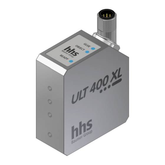
Layout and functional description Function > Sensor ULT 400 XL Layout and functional description 3.1 Function 3.1.1 Sensor ULT 400 XL Functional description The sensor monitors applied adhesive using infrared measurement technology. The sensor checks every product for proper adhesive application. The position and shape of adhesive tracks and adhesive dots are monitored. - Page 27 Layout and functional description Function > Sensor ULT 400 XL Status indicator Description GLUE Status indicator for adhesive moni- toring OBJECT Status indicator for product detec- tion On: There is a product under the sensor. Off: There is no product under the sensor.
- Page 28 Meaning READY OBJECT GLUE FLASHING FLASHING FLASHING Fault (red) (red) (red) Observe fault indications on the system controls. Switch sensor off and on again. Hardware error: – Replace the sensor. – Contact Baumer hhs service team. ULT 400 XL 04.05.2021...
- Page 29 Layout and functional description Function > Sensor ULT 400 XL Programming Meaning READY OBJECT GLUE FLASHING FLASHING A product without adhesive application was suc- cessfully programmed. (alternating (alternating green/blue) green/blue) FLASHING FLASHING Programming process for a product without adhe- sive application was unsuccessful. (alternating red/ (alternating red/ blue)
-
Page 30: Transport And Storage
Transport and storage Disposing of packaging materials Transport and storage 4.1 Delivery The packaging protects the individual components against trans- port damage, corrosion and other damage until installation. For this reason, do not destroy the packaging. The components and systems are packed in accordance with the expected transport conditions. - Page 31 Transport and storage Disposing of packaging materials ENVIRONMENT! Risk to the environment due to incorrect disposal Packaging materials are valuable raw materials and, in many cases, can continue to be used or sensibly reprocessed and sustainable reused. The incorrect dis- posal of packaging materials can result in risks to the environment.
-
Page 32: Assembly And Installation
Assembly and installation Assembly ULT 400 XL > Sensor ULT 400 XL Assembly and installation 5.1 Assembly ULT 400 XL 5.1.1 Sensor ULT 400 XL Personnel: Qualified mechanic Protective equipment: Protective work clothing Safety boots DANGER! Risk of injury when entering the operating space of the super-ordinate machine and its moving parts CAUTION! Risk of injury due to improper assembly and instal-... -
Page 33: Electrical Connection Ult 400 Xl
Assembly and installation Electrical connection ULT 400 XL > Sensor ULT 400 XL Ensure that the bottom edge of the sensor housing is 62,5 mm ± 12,5 mm from the adhesive track. Make sure that the sensor is tilted by a maximum of 20° to the adhesive track of the product. - Page 34 Assembly and installation Electrical connection ULT 400 XL > Sensor ULT 400 XL Detailed information on the electrical connection of the sensor can be found in the operating manual for the system control. Ensure the following before electrical connection: Only approved cables are used for the connections. All long or hanging cables are secured with an approved mounting system.
-
Page 35: Commissioning
Commissioning Commissioning ULT 400 XL > Sensor ULT 400 XL Commissioning Regulatory framework conditions for the owner Personnel: Owner In certain countries and regions, inspections must be carried out or authorization obtained before commissioning the equipment. Ensure that you are aware of the local regulations. Please refer to the authorities and institutes responsible before beginning production if authorization is required. - Page 36 Commissioning Commissioning ULT 400 XL > Sensor ULT 400 XL The sensor must be installed. Ä "Installation" on page 32 The sensor must be electrically connected. Ä “Electrical connection” on page 33 Configure the sensor settings on the system control. Further information on sensor settings can be found in the operating manual for the control.
-
Page 37: Operation
Operation Operation ULT 400 XL > Sensor ULT 400 XL Operation 7.1 Operation ULT 400 XL 7.1.1 Sensor ULT 400 XL NOTICE! Damage due to removal of sensor under voltage Removing the sensor from the system control cabinet under voltage may damage the electronics or cause a data loss. - Page 38 Operation Operation ULT 400 XL > Sensor ULT 400 XL Description GLUE Status indicator for adhesive moni- toring OBJECT Status indicator for product detec- tion READY Status indicator for the sensor 7.1.1.1 Sensor programming The sensor must be set up in the system control. Depending on the control system, most of the settings can be programmed.
- Page 39 Operation Operation ULT 400 XL > Sensor ULT 400 XL Meaning READY OBJECT GLUE FLASHING FLASHING A product with adhesive application was success- fully programmed. (alternating (alternating green/blue) green/blue) FLASHING FLASHING Programming process for a product with adhesive application was unsuccessful. (alternating red/ (alternating red/ blue)
- Page 40 Operation Operation ULT 400 XL > Sensor ULT 400 XL Meaning READY OBJECT GLUE The previous checked product is detected as error-free. (green) (green) (red) A product is currently under the sensor. Adhesive monitoring is overridden. Reliable adhesive detection cannot be ensured. The previous checked product is detected as faulty.
-
Page 41: Maintenance
Maintenance Maintenance work ULT 400 XL > Sensor ULT 400 XL Maintenance DANGER! Risk of injury when entering the operating space of the super-ordinate machine and its moving parts 8.1 Maintenance table Interval Maintenance work Personnel weekly ULT 400 XL: Operator Clean windows and protective glass for infrared measurement technology with a soft cloth. - Page 42 Maintenance Maintenance work ULT 400 XL > Sensor ULT 400 XL NOTICE! Property damage due to improper cleaning Unsuitable cleaning agents and methods can lead to material damage on the sensor and other components. – The lenses and protective glass of sensors should only be cleaned with a damp cleaning cloth.
-
Page 43: Fault Elimination
Fault elimination Fault table Fault elimination DANGER! Risk of injury when entering the operating space of the super-ordinate machine and its moving parts Possible causes for faults and fault correction tasks are described in the following chapter. If faults increasingly occur, shorten the maintenance interval according to the actual load. -
Page 44: Troubleshooting Ult 400 Xl
LEDs flash red. the sensor hardware. interface. Replace the sensor. Contact Baumer hhs service team. 9.2 Troubleshooting ULT 400 XL 9.2.1 Sensor ULT 400 XL The sensor monitors itself during operation. When faults occur, they are displayed in plain text in the system control. - Page 45 Meaning READY OBJECT GLUE FLASHING FLASHING FLASHING Fault (red) (red) (red) Observe fault indications on the system controls. Switch sensor off and on again. Hardware error: – Replace the sensor. – Contact Baumer hhs service team. 04.05.2021 ULT 400 XL...
-
Page 46: Disassembly And Disposal
In order to protect the environment and to ensure that electronic waste is disposed of correctly, Baumer hhs accepts voluntarily and at its discretion electronic and electrical waste devices for dis- posal under the following conditions: The customer delivers the waste devices to Baumer hhs with any shipping charges pre-paid. - Page 47 Disassembly and disposal Disposing of waste electrical an... Baumer hhs undertakes to dispose of its electronic and electrical waste devices correctly. Send the devices to the following address for disposal with shipping pre-paid: Baumer hhs GmbH Adolf-Dembach-Str. 19 47829 Krefeld...
-
Page 48: Technical Data
Technical data Technical data for the components > Sensor ULT 400 XL Sensor Technical data 11.1 Technical data for the components 11.1.1 Sensor ULT 400 XL Sensor Dimensions ULT 400 XL Fig. 1: Dimension sheet (mm) Data Value Unit Length 57 mm Width 24 mm... - Page 49 Technical data Technical data for the components > Sensor ULT 400 XL Sensor Data Value Unit Protection class IP 64 — Operating conditions Data Value Unit Temperature range 10 – 40 °C Relative humidity, maximum 70 % 04.05.2021 ULT 400 XL...
-
Page 50: Replacement Parts
Replacement parts Replacement parts ULT 400 XL > Sensor ULT 400 XL Replacement parts Wearing parts A wearing part is part of a component, or a component itself, that is designed in such a way that it will wear in time if used correctly. This increases the service life of the system itself substantially. - Page 51 Replacement parts Replacement parts ULT 400 XL > Sensor ULT 400 XL Extension cable: Item number Description 77743210 Extension cable 1.0 m 77743225 Extension cable 2.5 m 77743240 Extension cable 4.0 m 77743260 Extension cable 6.0 m 77743292 Extension cable 12.0 m 04.05.2021 ULT 400 XL...
-
Page 52: Index
Index Index Marking Safety ....... 12 Cleaning ULT 400 XL ......41 Commissioning Notification point . - Page 53 Index Technical data ULT 400 XL ......48 Technical limitations ..... . 11 Pressure .
Need help?
Do you have a question about the hhs ULT 400 XL and is the answer not in the manual?
Questions and answers