Table of Contents
Advertisement
Quick Links
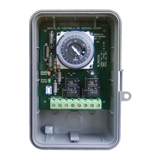
GM40 Series
Multi-Voltage Commercial
DPDT Time Switch
WARNING
• Disconnect power at the circuit breaker(s) or disconnect switch(es) before beginning
installation or servicing.
• More than one circuit breaker or disconnect switch may be required to de-energize the
equipment before servicing.
• Do not use the manual off position of the timer for equipment servicing. Always discon-
nect the power at the circuit breaker(s) or disconnect switch(es).
• Use COPPER conductors ONLY.
• For 40 amp loads, use #8 AWG wire, rated 90˚C min.
• Wire in accordance with national and local electrical code requirements.
CAUTION
• Rotate timer dial clockwise only.
UL TYPE 3R Enclosure
U.S. Patent #6,563,2371.
MAXIMUM CONTACT RATINgs PER POLE:
N.O. Contacts:
40A Resistive @ 120~277VAC
1HP, 16FLA, 90LRA @ 120VAC
2HP, 12FLA, 52LRA @ 208~277VAC
30A Ballast @ 120VAC
20A Ballast @ 277VAC
15A Tungsten @ 120VAC
300VA Pilot Duty 120~240VAC
N.C. Contacts:
30A Resistive @ 120~277VAC
1HP, 12FLA, 30LRA @ 120VAC
2HP, 10FLA, 30LRA @ 240VAC
2A Tungsten @ 120VAC
10A Ballast @ 277VAC
WIRINg CONNECTIONs:
Screw box lug terminals. Up to one #8 AWG
Wire.
ENVIRONMENTAL RATINgs:
Operating Temperature Range:
–40°F to 131°F (–40°C to 55°C)
Operating Humidity: 0 - 95% RH non-condensing
ENCLOsURE DIMENsIONs:
8.795" x 6.631" x 2.935" (H x W x D)
sHIPPINg WEIgHT: 3 lbs.
Agency Approvals: UL Listed
General Purpose
Risk of Fire or Electric Shock
Risk of Damage to Timer
INSTALLATION
Note: For outdoor locations, raintight or wet local conduit
hubs that comply with requirements of UL 514B (standard
for fittings for conduit and outlet boxes) must be used.
1. Open door and then remove interior protective
cover by releasing spring clip on bottom.
2. Remove timer mechanism by releasing spring clip
on bottom.
3. Select knockouts to be used. Remove inner 1/2"
knockout by inserting a screwdriver in the slot and
carefully punch knockout loose. Remove slug. If 3/4"
knockout is required, remove the outer ring with pliers
after removing the 1/2" knockout. Smooth edges with
knife if necessary.
4. Place enclosure in desired mounting location and
mark the three mounting holes (refer to diagram).
Start by placing set screw on top and attaching
enclosure over keyhole; then screw in remaining
two screws on bottom.
5. Connect conduit hubs to conduit before connecting the
hubs to the enclosure. After inserting hubs into enclo-
sure, carefully tighten hub lock nut. Do not over-torque.
6. Verify input voltage selection. Refer to DIP switch
diagram for desired input voltage.
7. Wire in accordance with National and Local Codes
(see wiring diagrams).
8. Grounding: Terminate all ground wires to ground
lug on bottom of enclosure.
9. Replace interior protective cover.
Interior
Protective
Cover
Step 1
INPUT VOLTAgE DIP sWITCH sETTINg:
1. Do not apply power to the gM40 prior to setting correct
Input Voltage DIP switch.
2. Determine the input voltage which will be applied to the GM40
(i.e. L1 and L2/N terminals, see wiring diagrams).
3. Set the DIP Switch according to the diagram below.
120VAC
208~240VAC
ON
OFF
ON
ON
ON
OFF
ON
ON
NOTE:
Unit is shipped with DIP Switches set for 277VAC Input Voltage.
1
TImer Mechanism
Step 2
277VAC (Default)
OFF
OFF
OFF
OFF
6-1/8"
2-1/2"
Ground Lug
Advertisement
Table of Contents

Related Manuals for Intermatic Grasslin GM40 Series


Summary of Contents for Intermatic Grasslin GM40 Series
- Page 1 GM40 Series General Purpose Multi-Voltage Commercial DPDT Time Switch Risk of Fire or Electric Shock WARNING • Disconnect power at the circuit breaker(s) or disconnect switch(es) before beginning installation or servicing. • More than one circuit breaker or disconnect switch may be required to de-energize the equipment before servicing. • Do not use the manual off position of the timer for equipment servicing. Always discon- nect the power at the circuit breaker(s) or disconnect switch(es). • Use COPPER conductors ONLY. • For 40 amp loads, use #8 AWG wire, rated 90˚C min. • Wire in accordance with national and local electrical code requirements. Risk of Damage to Timer CAUTION • Rotate timer dial clockwise only. INSTALLATION Note: For outdoor locations, raintight or wet local conduit hubs that comply with requirements of UL 514B (standard for fittings for conduit and outlet boxes) must be used.
- Page 2 MANUAL OVERRIDE: With the manual switch in the SPECIFIERS GUIDE middle position, the GM40 is in automatic mode and Furnish and install an Intermatic GM40 Multi-Volt Series 24 hour or (7 day) time switch with captive will switch at the programmed times. In the upper trippers and quartz or synchronous drive.
- Page 3 GM40 TERMINAL DESIGNATIONS TIMER COM2 Normally Open Normally Open (Isolated Contact) (Isolated Contact) Normally Closed Normally Closed L2/N (Isolated Contact) (Isolated Contact) GM40 TYPICAL WIRING DIAGRAMS Typical Wiring Diagram (120VAC Application) Typical Wiring Diagram (120VAC Application) Controlling One 120VAC Load Controlling Two 120VAC Loads TIMER TIMER...
- Page 4 LIMITED ONE YEAR WARRANTY If within the warranty period specified, this product fails due to a defect in material or workmanship, Intermatic Incorporated will repair or replace it, at its sole option, free of charge. This warranty is extended to the original purchaser only and is not transferable.
Need help?
Do you have a question about the Grasslin GM40 Series and is the answer not in the manual?
Questions and answers