Table of Contents
Advertisement
Quick Links
G-Vision 66
OPERATING INSTRUCTIONS MANUAL
codice: 81085_ 12-2021 - ENG
ATTENTION!
This manual must always be available to operators of the
devices described here.
Always make sure that you have the latest version of the
manual, which is available for free download from the GEFRAN
website (www.gefran.com).
Installers and/or maintenance personnel are required to read
this manual and to precisely follow the instructions contained
in it and in its attachments.
GEFRAN will not be liable for any damage to persons and/or
property, or to the product itself, caused by failure to follow
the instructions and observe the warnings given below.
This manual and its attachments may be freely reproduced
as long as they are not changed in any way and every copy
contains this warning and the declaration of ownership by
Gefran S.p.A.
Advertisement
Table of Contents

Related Manuals for gefran G-Vision 66-070

Summary of Contents for gefran G-Vision 66-070
- Page 1 GEFRAN will not be liable for any damage to persons and/or property, or to the product itself, caused by failure to follow the instructions and observe the warnings given below.
- Page 2 CODE UPDATE N. pages of the document Copyright © 2018 Gefran Soluzioni Subject to change without notice The information contained in this document is provided for informational purposes only. While efforts were made to verify the accuracy of the information contained in this documentation, it is provided “as is” without warranty of any kind.
-
Page 3: Table Of Contents
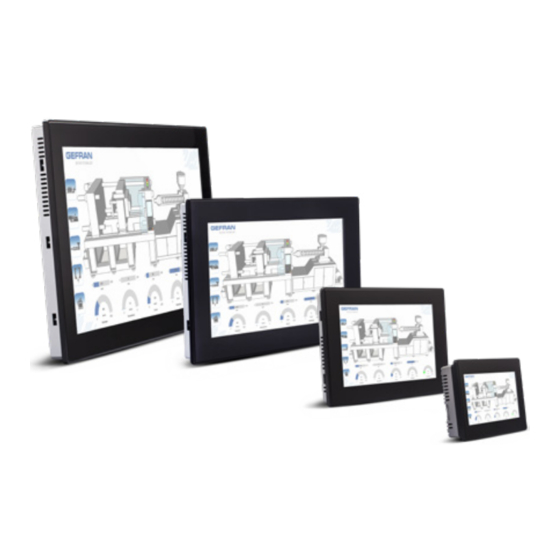
TABLE OF CONTENTS 1. PRODUCT OVERVIEW ........... 5 2. STANDARDS AND APPROVALS ........5 3. TECHNICAL SPECIFICATIONS ........7 4. TECHNICAL DATA ............9 4.1. Dimensions .............. 10 4.2. Installation Environment ......... 11 4.3. Safety instruction ............ 11 4.4. Installation Procedure ..........11 5. - Page 4 G-Vision 66-070 Operator interface with TFT color 7” widescreen display multitouch projected capacitive touchscreen G-Vision 66-101 Operator interface with TFT color 10.1” widescreen display multitouch projected capacitive touchscreen G-Vision 66-156 Operator interface with TFT color 15.6” widescreen display multitouch projected capacitive touchscreen G-Vision 66-215 Operator interface with TFT color 21.5”...
-
Page 5: Product Overview
IoT edge applications in factory, and for • Gateway function with OPC UA Server and Client. machine control. • Secure connectivity with Gefran Cloud and full network The glass projected capacitive touchscreen and the brilliant separation. displays with size up to 21.5” and resolution up to 1920x1080 •... - Page 6 An example of this plate is shown in the figure below: Note: the G-Vision label is used as an example for G-Vision Series MADE IN ITALY Gefran Soluzioni srl This product contains a battery. Dispose of the Via Sebina, 74 battery according 25050 Provaglio d’Iseo (BS) - ITALY...
-
Page 7: Technical Specifications
25 cycles (50Hz); 30 cycles (60Hz); Phase: 0°-180° Test executed on the 230Vac side of the EN 61000-4-11 Gefran Soluzioni Srl Power Supply Port: DC mains; Level: 0% duration: 10ms 20 spaces by 1s Test executed on the 24Vdc of the EUT... - Page 8 DURABILITY INFORMATION Backlight service life 40000 Hrs. or more (Time of continuos operation until the brightness of (LED type) the backlight reaches 50% of the rated value when the surrounding air temperature is 25°C) - see Note 1 SURFACE RESISTANCE Chemical resistance of the front glass for •...
-
Page 9: Technical Data
4. TECHNICAL DATA G-Vision G-Vision G-Vision G-Vision Model 66-070-54-00-00 66-101-54-00-00 66-156-54-00-00 66-215-54-00-00 System Resources 7 TFT 10.1 TFT 15.6 TFT 21,5 TFT Display - Colors 16:9 LED - 16M 16:9 LED - 16M LED - 16M LED - 16M Resolution 800x480 WVGA 1280x800 WXGA 1366x768, HD... -
Page 10: Dimensions
4.1. Dimensions MODEL G-Vision 66-070 187mm/7.36” 147mm/5.79” 176mm/6.90” 136mm/5.35” 47mm/1.85” 8mm/0.31” G-Vision 66-101 282mm/11.10” 197mm/7.80” 271mm/10.67” 186mm/7.32” 56mm/2.20” 8mm/0.31” G-Vision 66-156 422mm/16.60” 267mm/10.50” 411mm/16.18” 256mm/10.00” 56mm/2.20” 8mm/0.31” G-Vision 66-215 552mm/21.73” 347mm/13.66” 541mm/21.30” 336mm/13.22” 56mm/2.20” 8mm/0.31” 81085_G-Vision 66_12-2021_ENG... -
Page 11: Installation Environment
4.2. Installation Environment • the borders of the cutout must be flat Avoid prolonged exposition to direct sunlight to avoid the risk • screw up each fixing screw until the bezel corner get in of overheating the device. contact with the panel. The equipment is not intended for installation in contact with •... -
Page 12: Connections
5. CONNECTIONS G-Vision 66-070 G-Vision 66-101 G-Vision 66-156 G-Vision 66-215 1. USB Port V2.0, max. 500 mA 5. Ethernet port 0 (10/100/1000Mb) 2. Ethernet port 2 (10/100Mb) 6. Power Supply 3. Ethernet port 1 (10/100Mb) 7. 2x Expansion slot for Plugin module 4. -
Page 13: Ethernet Port
5.2. Ethernet Port The Ethernet port have two status indicators. Please see description in figure. Yellow Green OFF: Valid link has NOT been detected ON: No activity ON: Valid link has been detected BLINKING: Activity 5.3. Optional plugin module G-Vision panels have several optional plugin module, multiple modules configurations are possible.. Slot#2 and Slot#4 are available only if plugin module has the “bus extension connector”. -
Page 14: Optional Plugin Module Installation Procedure
5.4. Optional plugin module installation procedure Below you can find relation between modules and max number of modules that can be used into G-Vision 66 e GF_Connect devices, based on their Interface Type: Bus Extension Module Application Max Modules Interface Type connector GV_PLUG-CAN GV_PLUG-3G... -
Page 15: Power Supply, Grounding And Shielding
6. POWER SUPPL Y , GROUNDING AND SHIELDING The power supply terminal block is shown in the figure below. Figure 6.1 3 conductor 1,5mmq wire size minimum, minimum temperature conductor rating 105°C. Note: The power supply circuit may be floating or grounded. In the Ensure that the power supply has enough power capacity for the operation of the equipment. -
Page 16: Battery
When the battery is fully charged, it ensures a period of 3 • hardware real-time clock (date and time) months of data back-up at 25°C. Battery Figure 7.1: G-Vision 66-070, G-Vision 66-101, G-Vision 66-156, G-Vision 66-215 ATTENTION ATTENTION Dispose of batteries according to local This device cannot be disposed of as regulations. -
Page 17: System Settings
needs to reboot and will be ready to download the application • USB Create an Update Package using GF directly from GF Project VX. Designer HD and copy it to a USB Flash drive. Insert the USB key in the G-Vision If you are planning to use your G-Vision with GF Designer HD and proceed in “Application”... - Page 18 Note: Additional informations on System Settings are the device power-up phase. Tapping available in dedicated manual frequency must be high. https://www.gefran.com You have to start tapping the touchscreen as soon as power has been applied to the device. When the sequence has been recognized, the system shows the message: “TAP-TAP...
-
Page 19: Unpacking And Packing Instructions
11. UNPACKING AND PACKING INSTRUCTIONS Figure 11.1: G-Vision 070, G-Vision 101 Figure 11.2: G-Vision 156, G-Vision 215 To repack the unit, please follow the instructions backwards. 81085_G-Vision 66_12-2021_ENG... - Page 20 Gefran Soluzioni srl Via Sebina 74 - 25050 Provaglio d’Iseo (BS) Italy Tel. +39 0309888.1 - Fax +39 0309839063 - info@gefran.com http://www.gefran.com www.gefran.com/en/gefran-soluzioni...
Need help?
Do you have a question about the G-Vision 66-070 and is the answer not in the manual?
Questions and answers