Table of Contents
Advertisement
Quick Links
© Copyright 2019
EVERTZ MICROSYSTEMS LTD.
5292 John Lucas Drive
Burlington, Ontario
Canada L7L 5Z9
Phone:
+1 905-335-3700
Sales:
sales@evertz.com
Tech Support: service@evertz.com
Web Page:
http://www.evertz.com
Version 0.1, June 2019
The material contained in this reference guide consists of information that is the property of Evertz Microsystems and is intended solely for the use
of purchasers of the 9821EMR-AG-HUB product. Evertz Microsystems expressly prohibits the use of this guide for any purpose other than the
operation of the contained in this reference guide consists of information that is the property of Evertz Microsystems and is intended solely for the
use of purchasers of the 9821EMR-AG-HUB product. Due to on going research and development, features and specifications in this manual are
subject to change without notice.
All rights reserved. No part of this publication may be reproduced without the express written permission of Evertz Microsystems Ltd. Copies of
this manual can be ordered from your Evertz dealer or from Evertz Microsystems.
9821EMR-AG-HUB
User Manual
Fax: +1 905-335-3573
Fax: +1 905-335-7571
Advertisement
Table of Contents

Related Manuals for evertz 9821EMR-AG-HUB


Summary of Contents for evertz 9821EMR-AG-HUB
- Page 1 Version 0.1, June 2019 The material contained in this reference guide consists of information that is the property of Evertz Microsystems and is intended solely for the use of purchasers of the 9821EMR-AG-HUB product. Evertz Microsystems expressly prohibits the use of this guide for any purpose other than the operation of the contained in this reference guide consists of information that is the property of Evertz Microsystems and is intended solely for the use of purchasers of the 9821EMR-AG-HUB product.
- Page 2 This page left intentionally blank...
- Page 3 IMPORTANT SAFETY INSTRUCTIONS The lightning flash with arrowhead symbol within an equilateral triangle is intended to alert the user to the presence of uninsulated “Dangerous voltage” within the product’s enclosure that may be of sufficient magnitude to constitute a risk of electric shock to persons. The exclamation point within an equilateral triangle is intended to alert the user to the presence of important operating and maintenance (Servicing) instructions in the literature accompanying the product.
- Page 4 WARNING Changes or Modifications not expressly approved by Evertz Microsystems Ltd. could void the user’s authority to operate the equipment. Use of unshielded plugs or cables may cause radiation interference. Properly shielded interface cables...
-
Page 5: Table Of Contents
2.3.2. Connections for the Back of the unit ................6 CONFIGURATION ......................... 7 3.1. SETTING IPS ON FCS......................7 9821EMR-AG-HUB WEB INTERFACE ..................9 4.1. SYSTEM ..........................10 4.1.1. Control Port Configuration ..................10 4.1.2. Data Port Configuration ................... 10 4.1.3. - Page 6 9821EMR-AG-HUB User Manual 4.6.4. IP Output Advanced Control ..................24 4.7. IP INPUT (S302M) ......................24 4.7.1. Global Control ......................25 4.7.2. Express IP Input ...................... 25 4.7.3. IP Input Control ....................... 25 4.7.4. RTP Control ......................26 4.8. IP INPUT (AES67) ......................26 4.8.1.
- Page 7 6.1. 9821EMR-AG-HUB UPGRADE ..................43 6.2. 9821EMR-IO-DANTE-64 UPGRADE .................. 43 6.3. 9821EMR-FC UPGRADE ....................44 FIGURES Figure 2-1 : 9821EMR-AG-HUB Front Panel Connections ............. 3 Figure 2-2 : 9821EMR-AG-HUB Rear Panel Connections.............. 3 Figure 4-1 : WebEASY - Login Menu .................... 9 ®...
- Page 8 ® Figure 5-11 : WebEASY - 9821EMR-FC\Dante TDM In and Out Status ........41 ® Figure 6-1 : WebEASY - 9821EMR-AG-HUB Top Menu Bar ............43 ® Figure 6-2 : WebEASY - 9821EMR-AG-HUB Firmware Upgrade ..........43 ® Figure 6-3 : WebEASY - 9821EMR-FC Top Menu Bar ...............
- Page 9 9821EMR-AG-HUB User Manual This page left intentionally blank TABLE OF CONTENTS Page - v Revision 0.1...
- Page 10 Evertz products are for informational use only and are not warranties of future performance, either expressed or implied. The only warranty offered by Evertz in relation to this product is the Evertz standard limited warranty, stated in the sales contract or order confirmation form.
- Page 11 9821EMR-AG-HUB User Manual This page left intentionally blank TABLE OF CONTENTS Page - vii Revision 0.1...
-
Page 13: Overview
The 9821EMR-AG-HUB provides a gateway to link IP infrastructures with discrete audio IO directly and by using any of the existing Evertz TDM enabled Audio interfaces. It has a number of functional use cases including translating between AoIP standards including SMPTE ST 302M, AES67* and Dante, for audio bridging between devices supporting SMPTE ST 302M or AES67* to a common core IP audio format. - Page 14 9821EMR-AG-HUB User Manual This page left intentionally blank Page - 2 Revision 0.1...
-
Page 15: Physical Connection
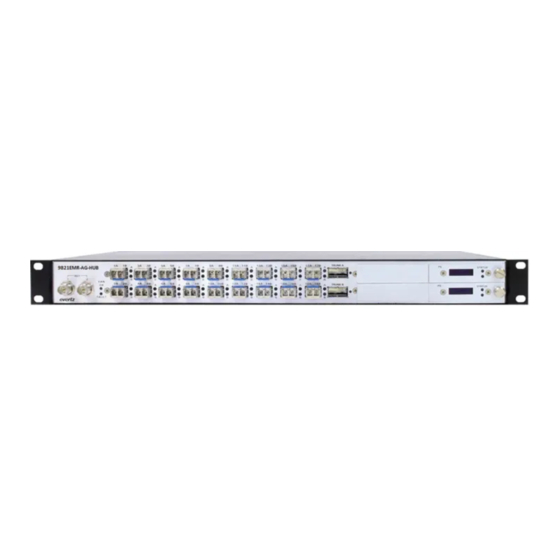
9821EMR-AG-HUB User Manual PHYSICAL CONNECTION 9821EMR-AG-HUB is occupying 1RU rack space and there are connections at the back and front of the unit for different purposes. 2.1. FRONT PANEL Figure 2-1 : 9821EMR-AG-HUB Front Panel Connections Front of the unit has the following connections:... -
Page 16: System Wiring
9821EMR-AG-HUB User Manual 2.3. SYSTEM WIRING The unit can be wired based on the application; but in this section all possible connections will be described. 2.3.1. Connections for the front of the unit 2.3.1.1. SFPs These SFPs are used for TDM or MADI connections and the SFPs could be Fiber or Mini din. - Page 17 9821EMR-AG-HUB User Manual For version above 67 the mapping is one to one. Page - 5 Revision 0.1...
-
Page 18: Connections For The Back Of The Unit
There are two Ethernet ports between the two power connectors: The top RJ45 will be used to access 9821EMR-AG-HUB, upgrading and out-band connection to SDVN. The bottom RJ45 will be used to access 9821EMR-FC, the Dante modules and upgrading them. -
Page 19: Configuration
To set the bottom FC IP, connect the Micro USB to the bottom FC and open Teraterm. Login as root/evertz and then type “console” and from there change the IPs. Once the IP on both FCs are configured, reboot the entire unit for the changes to take effect. - Page 20 9821EMR-AG-HUB User Manual This page left intentionally blank Page - 8 Revision 0.1...
-
Page 21: 21Emr-Ag-Hub Web Interface
User Manual 9821EMR-AG-HUB WEB INTERFACE 9821EMR-AG-HUB is accessed via the top FC. It can be operated and controlled via Webeasy. To access the Webeasy page, simply type the IP address of the control port of 9821EMR-AG-HUB module in the web browser's address bar on your PC which is on management network. -
Page 22: System
9821EMR-AG-HUB User Manual 4.1. SYSTEM Figure 4-3 : WebEASY - System (Part 1) ® 4.1.1. Control Port Configuration This section allows the user to configure the Control IP address (FC) of the unit. 4.1.2. Data Port Configuration This section allows the user to configure the Data Port IP addresses of the unit for in-band communication. -
Page 23: Data Port Monitor
9821EMR-AG-HUB User Manual 4.1.3. Data Port Monitor This section shows the link and data flow status for each connection. Ethernet Rx Bandwidth: This parameter displays the received Ethernet Bandwidth in Mbps. Ethernet Rx Frames Ok: This parameter displays the number of Error-Free frames received. -
Page 24: Sfp Control
9821EMR-AG-HUB User Manual Figure 4-4 : WebEASY - System (Part 2) ® 4.1.4. SFP Control In this section, the SFP detection can be set manually or set by magnum automatically. 4.1.5. Genlock Control In this section the user can select between reference 1 or 2. Currently only reference 1 is active. -
Page 25: In-Band Control
9821EMR-AG-HUB User Manual 4.1.6. In-band Control In this section, the user can select the SFPs for main and backup in-band control. E.g: QSFP1.1 and 2.1 are set as main and backup for S302M; 1.3 and 2.3 are set as main and backup for AES67. -
Page 26: Crosspoint Control
9821EMR-AG-HUB User Manual 4.3. CROSSPOINT CONTROL 4.3.1. Configuration Guide Figure 4-6 : WebEASY - Crosspoint Control\Configurable Guide ® Figure 4-7 shows the signal follow “from” and “to” the unit. If the signal flow is from Dante to TDM or vice versa, the TDM input and output status will not report under signal input and signal output. -
Page 27: Crosspoint Control
9821EMR-AG-HUB User Manual Figure 4-7 : Configuration Guide Diagram 4.3.2. Crosspoint Control In this section, the user needs to configure the correct crosspoint based on the system requirement. The left column shows the sources and the top row shows the destination. An input can be routed any output and multiple outputs can have the same input at the same time. -
Page 28: Figure 4-8 : Webeasy
9821EMR-AG-HUB User Manual Figure 4-8 : WebEASY - Crosspoint Control\Dante to Dante, IP and TDM ® AES67 or S302M to Dante AES67 or S302M to AES67 or S302M AES67 or S302M to TDM/MADI Figure 4-9 : WebEASY - Crosspoint Control\IP to DANTE, IP and TDM/MADI ®... -
Page 29: Figure 4-10 : Webeasy - Crosspoint Control\Tdm To Dante, Ip And Tdm/Madi
9821EMR-AG-HUB User Manual TDM to DANTE TDM or MADI to AES67 or S302M TDM to TDM or MADI to MADI Figure 4-10 : WebEASY - Crosspoint Control\TDM to Dante, IP and TDM/MADI ® MADI to Dante or Dante to MADI is not currently supported. -
Page 30: Figure 4-11 : Webeasy
9821EMR-AG-HUB User Manual Figure 4-11 : WebEASY - Crosspoint Control\Dante TDM ® Figure 4-12 : WebEASY - Crosspoint Control\ AES67/S302M Dante ® Page - 18 Revision 0.1... -
Page 31: Figure 4-13 : Webeasy - Crosspoint Control\ Aes67/S302M Tdm/Madi
9821EMR-AG-HUB User Manual Figure 4-13 : WebEASY - Crosspoint Control\ AES67/S302M TDM/MADI ® The unidirectional routes can be combined to accomplish multi-directional routes e.g.: Dante TDM AES67 TDM Dante AES67 To be able to make route to or from 9821, user may need to use both SDVN and CH to accomplish all. -
Page 32: Signal Input
9821EMR-AG-HUB User Manual 4.4. SIGNAL INPUT Figure 4-14 : WebEASY - Signal Input ® 4.4.1. Global Control This section allows the user to enable or disable the pop suppression globally. POP suppression is used for reducing the pop/click sound when the audio switch happens in upstream path. -
Page 33: Channel Monitoring
9821EMR-AG-HUB User Manual TDM Source Detected: This parameter displays the status of the TDM Input Presence TDM Source Identifier: This parameter displays the TDM Input Source comes from. MADI Source Detected: This parameter displays the status of the MADI Input Presence. -
Page 34: Express Ip Output
9821EMR-AG-HUB User Manual 4.5.1. Express IP Output Allows the user to set the Multicast address range and port# for each individual TDM port and purge it. 4.5.2. IP Output Control This section displays the current Multicast addresses and UDP ports. -
Page 35: Global Control
Short packet times allow for lower latency but introduce overhead and high packet rates that may overtax some devices or networks. Long packet times imply higher latency and require additional buffering which may not be available on memory-constrained devices. 9821EMR-AG-HUB supports 1ms and 125µs packet time for AES67. -
Page 36: Express Ip Output
9821EMR-AG-HUB User Manual The audio will be muted or will not be clean when PTP is not present. When "IP Output Mute If PTP is Unlocked" option is disabled, the Delay control has to be set to manual. 4.6.2. Express IP Output This section allows the user to set the Multicast Addresses range and UDP Ports for each TDM and purge it. -
Page 37: Global Control
9821EMR-AG-HUB User Manual Figure 4-17 : WebEASY - IP Input (S302M) ® 4.7.1. Global Control SFP Redundancy Selection: This field allows the user to see whether the traffic for IP to TDM Output path is on QSFP1.1 or QSFP2.1, QSFP1.2 or QSFP2.2 4.7.2. -
Page 38: Rtp Control
9821EMR-AG-HUB User Manual 4.7.4. RTP Control This mode is used for filtering the RTP header and it is applied for entire TDM Outputs. For instance, if the incoming IP packets don’t have RTP Header, and does want to pass audio through TDM Outputs, then select “NO”... -
Page 39: Ip Input Control
9821EMR-AG-HUB User Manual 4.8.3. IP Input Control This section allows the user to see and set the Multicast Address and UDP Port for the each Transport Stream in each Link. Also it displays the status of the IP Input and RTP Sequence Errors. -
Page 40: Dealy Control
9821EMR-AG-HUB User Manual 4.10. DEALY CONTROL Figure 4-20 : WebEASY - Delay Control ® 4.10.1. Global Delay Control Network Delay for Auto Mode: Adjusts for end-to-end delay from Encap to Decap. Audio streams take minimum 3ms to be Encap'd, travel thru network, reach Decap unit, and go into memory, before they can be played out as TDM. -
Page 41: Pcr Control
9821EMR-AG-HUB User Manual 4.11. PCR CONTROL Figure 4-21 : WebEASY - PCR Control ® 4.11.1. PCR Output Control In this section the user can set the device to generate PCR stream. PCR Output PID: This parameter allows the user to set the time reference PCR PID. -
Page 42: Time Reference
9821EMR-AG-HUB User Manual 4.11.3. Time Reference Jitter Tolerance: This parameter allows the user to set the jitter tolerance. 4.12. PTP CONTROL In this section, the user can set the SFP ports, Domain Number, Priority1 and 2 for incoming PTP also the incoming PTP status can be monitored. -
Page 43: Reference Notify
9821EMR-AG-HUB User Manual Status: Shows if the device is converged to the incoming PTP or not. Announce Received: Shows the numbers of PTP announcements have been received. Announce Lost: Shows if any announcement has been lost. It should be zero. -
Page 44: Pcr Notify
9821EMR-AG-HUB User Manual 4.13.2. PCR Notify PCR Present: Allows the user to set the trap for PCR Present to True or False for main and backup paths. PCR Increment Errors: Allows the user to set the trap for PCR Increment Errors to True or False for main and backup path. -
Page 45: Notify
9821EMR-AG-HUB User Manual 4.14. NOTIFY In this section, the user can set the following: Temperature Threshold for trap Set the trap to true or false for Board Temperature Set the trap to True or False for Ethernet and Input Signal Fault... -
Page 46: Snmp Trap
9821EMR-AG-HUB User Manual 4.15. SNMP TRAP In this section the user can view, add or remove trap destinations. Figure 4-25 : WebEASY - SNMP Trap ® Page - 34 Revision 0.1... -
Page 47: 21Emr-Fc Web Interface
9821EMR-AG-HUB User Manual 9821EMR-FC WEB INTERFACE 9821EMR-FC is the bottom FC and the web-easy can be access by typing the IP address of the FC in address bar of the browser. The following menus are available on the web-easy page:... -
Page 48: Time Management
9821EMR-AG-HUB User Manual Set the Control, Netmask and Gateway IP addresses for the module. Set the Trap Destination The “Magnum Control” section is currently not being configured or used Figure 5-3 : WebEASY - 9821EMR-FC\Network management ® 5.3. TIME MANAGEMENT In this section the user can set the time source to local or NTP server. -
Page 49: Sfp
9821EMR-AG-HUB User Manual 5.4. In this section both the regular SFPs and QSFPs status are monitored. For SFPs there are 18 slots and each slot there is information about the SFP Presence, Connector type, Name, Serial Number, firmware version temperature and supply voltage. -
Page 50: Module Configuration
9821EMR-AG-HUB User Manual Dante module 1 will occupy slots 3 and 5, but only slot 3 shows status. Dante module 2 will occupy slots 4 and 6, but only slot 6 shows status. Dante module 3 will occupy slots 7 and 9, but only slot 7 shows status. -
Page 51: Figure 5-9 : Webeasy - 9821Emr-Fc\Module Configuration
9821EMR-AG-HUB User Manual Figure 5-9 : WebEASY - 9821EMR-FC\Module Configuration ® Dante 1 Module Information: In section the firmware and software version of the Dante card itself is being shown as well. Dante 1 Module Control and Status: The switch mode should be set to Redundant since there is main and redundant Ethernet port for each module. -
Page 52: Figure 5-10 : Webeasy - 9821Emr-Fc\Dante Module Information
9821EMR-AG-HUB User Manual Figure 5-10 : WebEASY - 9821EMR-FC\Dante Module Information ® Audio Control & Status: In this section it shows whether the Module receives or transmits audio. If “TDM 1 Audio Channel XX Output” is green, it means the Dante Module is receiving Dante from a Dante device and sending it to 9821 as TDM. -
Page 53: Figure 5-11 : Webeasy - 9821Emr-Fc\Dante Tdm In And Out Status
9821EMR-AG-HUB User Manual Figure 5-11 : WebEASY - 9821EMR-FC\Dante TDM In and Out Status ® Page - 41 Revision 0.1... - Page 54 9821EMR-AG-HUB User Manual This page left intentionally blank Page - 42 Revision 0.1...
-
Page 55: Firmware Upgrade
9821EMR-AG-HUB User Manual FIRMWARE UPGRADE 6.1. 9821EMR-AG-HUB UPGRADE To upgrade the card, the user needs to log as admin/admin or root/evertz to gain access to upgrade menu. Figure 6-1 : WebEASY - 9821EMR-AG-HUB Top Menu Bar ® Once the upgrade option is selected, the upgrade page will open and display the current firmware version installed. -
Page 56: 9821Emr-Fc Upgrade
Figure 6-4 : WebEASY - 9821EMR-IO-DANTE-64 Firmware Upgrade ® 6.3. 9821EMR-FC UPGRADE To upgrade the 9821EMR-FC, the user needs to log as admin/admin or root/evertz to gain access to upgrade menu. Figure 6-5 : WebEASY - 9821EMR-FC Top Menu Bar ®... -
Page 57: 9821Emr-Fc Firmware Upgrade
9821EMR-AG-HUB User Manual To upgrade or downgrade the FC modules, user needs to click on the Browser button and locate the “9821EMR-FC_XXXVXXXX_BXXX.tar.gz” file. Once the file is selected, press the Upgrade button. The “tar.gz” file will be uploaded and installed and at the end of the upgrade the modules will reboot automatically. - Page 58 9821EMR-AG-HUB User Manual End of Document Page - 46 Revision 0.1...
Need help?
Do you have a question about the 9821EMR-AG-HUB and is the answer not in the manual?
Questions and answers