ADTRAN T200 H4TU-R Troubleshooting Manual
Hide thumbs
Also See for T200 H4TU-R:
- Installation and maintenance practice (26 pages) ,
- Specifications (2 pages) ,
- Installation and maintenance practice (28 pages)
Table of Contents
Advertisement
Quick Links
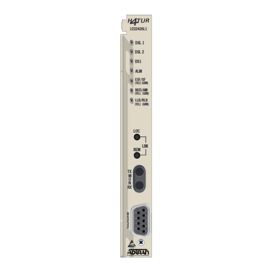
T200 H4TU-R
LED STATUS
DSL 1
CLEI: T1L5JZTC_ _
DSL 2
DS1
1222426L1
ALM
DSL 1
ESF / SF
DSL 2
DS1
B8ZS / AMI
ALM
LLB / RLB
ESF/SF
(YEL)
(GRN)
B8ZS/AMI
OPTIONS
(YEL)
(GRN)
LLB/RLB
Front Panel Buttons
(YEL)
(GRN)
Initiates a bidirectional loopback of the H4TU-R toward the network and customer
LOC
REM
Initiates a loopback at the H4TU-C toward the customer
POWER
LOC
This specific unit is intended for span power only. If a locally powered unit is needed, refer to P/N 1221424L1.
LBK
REM
DS1 MONITOR JACKS
DS1 signal from CPE toward Network (nonintrusive)
TX
RX DS1 signal from Network toward CPE (nonintrusive)
TX
M
O
COMPLIANCE
N
RX
Warning: Up to –200 VDC may be present on telecommunications wiring. Ensure chassis ground is properly connected.
This product is intended for installation in restricted access locations only and in equipment with a Type "B" or
"E" enclosure.
This product meets all requirements of Bellcore GR-1089-CORE (Class A2), ANSI T1.418-2002 and is NRTL listed to
R
S
the applicable UL standards.
2
3
2
Code
Power Code (PC)
Telecommunication Code (TC) X
Installation Code (IC)
C A U T I O N !
C A U T I O N
SUBJECT TO ELECTROSTATIC DAMAGE
OR DECREASE IN RELIABILITY.
HANDLING PRECAUTIONS REQUIRED.
DSL Loop 1 sync, no errors currently detected, and signal margin ≥ 3 dB
Green
Red
No DSL Loop 1 sync, errors being detected, or signal margin < 3 dB
DSL Loop 2 sync, no errors currently detected, and signal margin ≥ 3 dB
Green
Red
No DSL Loop 2 sync, errors being detected, or signal margin < 3 dB
Green
DSX-1 signal is present and no errors currently being detected
Red
No DSX-1 signal or signal is present with errors
Off
No active alarm present
Yellow
Loss of DS1 signal to the remote
Red
Loss of DSX-1 signal to the unit
Off
Unit has detected UNFRAMED data
Green
Unit has detected SF data
Yellow
Unit has detected ESF data
Green
Unit has detected AMI data
Yellow
Unit has detected B8ZS coded data
Off
Unit is NOT in loopback
Yellow
Unit is in loopback (network and/or customer)
Input Output
C
C
X
A
–
For a complete Installation and Maintenance Practice (P/N 61222426L1-5): 877-457-5007, Faxback Document 853. Please have your fax number ready.
T200 H4TU-R
JOB
61222426L1-22C
CARD EDGE PIN ASSIGNMENTS
Chassis Ground
1
2
3
4
DS1 TX Tip
5
6
HDSL4 Tip (Loop 1)
7
8
9
10
Chassis Ground
11
GND Protection Switching
12
HDSL4 Ring (Loop 1)
13
14
DS1 TX Ring
15
16
17
18
19
VCC
20
21
22
23
24
25
26
Chassis Ground
27
28
29
30
31
32
33
34
35
36
37
38
39
Protection Switching
40
HDSL4 Tip (Loop 2)
41
42
43
44
45
46
HDSL4 Ring (Loop2)
47
48
DS1 RX Ring
49
50
51
52
53
54
DS1 RX Tip
55
A
ID
0311
Advertisement
Table of Contents

Related Manuals for ADTRAN T200 H4TU-R


Summary of Contents for ADTRAN T200 H4TU-R
- Page 1 T200 H4TU-R 61222426L1-22C 0311 T200 H4TU-R CARD EDGE PIN ASSIGNMENTS LED STATUS DSL Loop 1 sync, no errors currently detected, and signal margin ≥ 3 dB DSL 1 Green Chassis Ground CLEI: T1L5JZTC_ _ No DSL Loop 1 sync, errors being detected, or signal margin < 3 dB DSL Loop 2 sync, no errors currently detected, and signal margin ≥...
- Page 2 Network Arming Pattern. If Smartjack LB is enabled, HTU-R will loop toward network. and set for 1.2 to 19.2 kbps, 8 data bits, no parity, 1 stop bit, no flow control. Select “3” from the ADTRAN HDSL4 Main Menu 2in6 H4R LB to Network.
Need help?
Do you have a question about the T200 H4TU-R and is the answer not in the manual?
Questions and answers