Table of Contents

Related Manuals for Morgana DocuMaster MFC


Summary of Contents for Morgana DocuMaster MFC
- Page 1 Part Number: 190-98 Issue 1a - April 2013 DocuMaster MFC Service ManuaI Multi-Feed & Crease Bookletmaking System Morgana Systems Limited ¤ United Kingdom ¤ www.morgana.co.uk ¤ Tel: +44 (0)1988 608888 ¤ Fax: +44 (0)1988 692399...
- Page 2 Reproduction, adaptation, or translation without prior written permission is prohibited, except as allowed under the copyright laws. Morgana Systems Limited shall not be liable for errors contained herein or for incidental or consequential damage in connection with the furnishing, performance or use of this material.
-
Page 3: Table Of Contents
4.2.7 Remove the Rear Guard ....................45 4.2.8 Remove the Input Guide ....................45 4.2.9 Remove the Motor Cover ....................46 4.2.10 Remove the Motor Cover Base Plate ................47 4.2.11 Remove the Gathering Area Centre Guard ..............47 Morgana DocuMaster MFC - Service Manual... - Page 4 4.8.3 Replace the Feed Clutch ....................123 4.8.4 Replace the Tray Lift Motor Assembly ................124 4.8.5 Replace the Air/Vacuum Solenoid Valve ................124 4.8.6 Replace the Paper Stop Fingers..................126 4.8.7 Replace the Feed Bin Control PCB .................. 127 Morgana DocuMaster MFC - Service Manual...
- Page 5 4.14.4 The Suction Feed Bin Maintenance Schedule ..............184 4.14.5 The Friction Feed Bin Maintenance Schedule..............185 4.14.6 The Creaser Module Maintenance Schedule ..............186 4.14.7 The Gathering Area Maintenance Schedule ..............186 4.14.8 The Electrical Cabinet Maintenance Schedule ..............187 Morgana DocuMaster MFC - Service Manual...
- Page 6 7.6 GUI CPU Software Updates through an RS232 Connection..........232 7.6.1 Install the GUI Software through an RS232 Connection ........... 233 7.6.2 Update the GUI Software through an RS232 Connection ..........235 7.7 GUI PCPU Software Updates through a Network Connection ..........236 Morgana DocuMaster MFC - Service Manual...
- Page 7 8.3.4 Connect the Booklet-Maker System .................. 255 8.3.5 Turn on the Booklet-Maker System ................... 256 8.3.6 Turn on the MFC....................... 256 8.3.7 Make Some Book Samples ....................257 8.3.8 Check the Book Quality ....................257 Morgana DocuMaster MFC - Service Manual...
- Page 8 CONTENTS Morgana DocuMaster MFC - Service Manual...
- Page 9 Introduction SECTION 1 Morgana DocuMaster MFC - Service Manual...
-
Page 10: Introduction
1. Introduction - Introduction Introduction Introduction The Morgana DocuMaster MFC (Multi-Feed Creaser) booklet making system automatically gathers sheets of pre-collated, sequentially printed paper and transfers them to an online bookletmaker to produce saddle stapled booklets with a SquareBack™ finish. The MFC can be programmed to insert heavier cover-weight... -
Page 11: Safety
1. Introduction - Safety Safety Follow good Health and Safety procedures when you lift or move the equipment. If the machine is operated when the covers are removed, be careful to prevent personal injury. Morgana DocuMaster MFC - Service Manual... -
Page 12: Warnings
Warning: a WARNING message tells you that a procedure or operation can be dangerous. To prevent injury, you must obey the instructions. Caution: a CAUTION message tells you that a procedure or operation can damage the machine. to prevent damage, you must obey the instruction. Morgana DocuMaster MFC - Service Manual... -
Page 13: Warning Labels
1. Introduction - Warning Labels Warning Labels The warning labels that follow are used in the DocuMaster MFC. Warning Labels Description Location Shows an entanglement hazard. Hinged rear Black illustration on yellow panel above the triangle. rear guard. Black text on orange caution bar and white background. -
Page 14: Orientation
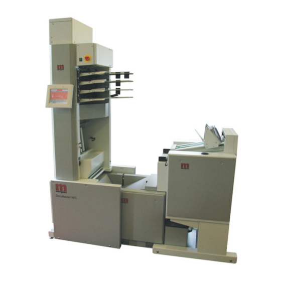
• The GUI touch screen is at the left • The conveyor is at the rear. GUI Touch Screen Rear LH Side RH Side Front Emergency Stop Switch BookletMaker Figure 1.1 DocuMaster MFC Orientation Morgana DocuMaster MFC - Service Manual... -
Page 15: Machine Covers
• hinged front panel • hinged rear panel • motor cover • electrical cabinet cover • LH side covers • RH side covers • CAP rear panel • gathering area centre guard. Morgana DocuMaster MFC - Service Manual... -
Page 16: Safety Interlocks
1. Introduction - Safety Interlocks Safety Interlocks The DocuMaster MFC has safety interlocks that: • Protect the operator when the machine is open for maintenance or to clear a jam. • Protect a service technician when the machine is open for service procedures. -
Page 17: The Emergency Stop Switch
The rear guard interlock removes the drive signal when the rear guard is removed from the MFC. These systems do not operate when the rear guard is removed: • the conveyor drive • the creaser conveyor drive. Morgana DocuMaster MFC - Service Manual... -
Page 18: Machine Overview
Trimmer BookletMaker Figure 1.5 DocuMaster MFC with Online Booklet Maker and SquareBack System 1. The CAP (Combined Air Pump): The CAP module includes the blower and the vacuum motors in an enclosed acoustically-insulated box. The internal temperature of the CAP is controlled by forced-air cooling operated by a thermostat sensor. - Page 19 The sheets are controlled with a combination of conveyor guides and a variable pressure air knife to make sure that they gather neatly and remain in the correct order. Morgana DocuMaster MFC - Service Manual...
- Page 20 AC power supply is removed. The components in the electrical cabinet are the: • creaser controller PCB • stepper-motor control PCBs • DC PSUs (Power Supply Units) • fuses • diagnostic interface plug. Morgana DocuMaster MFC - Service Manual...
-
Page 21: Description Of Operation
GUI to overcome problems caused by print variations (see About the Machine, in the DocuMaster MFC User Operating Instructions Manual). When the sheet is in the conveyor guides, the emitter is turned on and the sensor receives more light through a low density sheet, and less light through a high density sheet. -
Page 22: The Paper Feed
CPU uses the PWM master timing signal from the creaser controller PCB to synchronise all the MFC operations that occur in the feed cycle. When a feed bin has received a feed trigger it starts its feed cycle. Morgana DocuMaster MFC - Service Manual... - Page 23 SDET value is 15.2mm, so by default, the sensor check for a trailing error occurs 15.2mm after the calculated back edge of the sheet. If the SDET value is adjusted, the sensor check for trailing errors will automatically change. Morgana DocuMaster MFC - Service Manual...
-
Page 24: The Creaser
The skew angle of the sheet. The DynaTilt mechanism is adjusted by a 24V stepper-motor. The mechanism is calibrated to a home position switch when the creaser module is first turned on or started. Morgana DocuMaster MFC - Service Manual... -
Page 25: The Gathering Area
When all of the sheets of a set (booklet) have been gathered, an EOS (End Of Set) signal is sent from the CPU to the base control pcb. The base control PCB operates a solenoid that is connected to the paper stop latch. The stop latch is pulled open, which Morgana DocuMaster MFC - Service Manual... - Page 26 A reed switch sensor above the paper stop latch detects the paper in the gathering area. If the sensor detects paper at the end of the release sequence, the paper stop latch will remain open and the MFC will show a jam error. Morgana DocuMaster MFC - Service Manual...
-
Page 27: Error Conditions
Error Conditions SECTION 2 Morgana DocuMaster MFC - Service Manual... -
Page 28: Mfc Error Procedure
PCB is not connected. connections (See Section 7.1.1). The MFC shows a ‘Error Fuse F2 is defective. Replace the fuse (see Section 7.1.1). on 28V Rail’ error message The 20-way cable is defective. Replace the 20-way cable. Morgana DocuMaster MFC - Service Manual... -
Page 29: Blower Motor Problems
The blower motor is overheating. Check the CAP cooling system (see stopped, then starts Section 4.4.1). again after some time. Check the air filter (see Section 4.7.7). Replace the blower motor (see Section 4.6.2). Morgana DocuMaster MFC - Service Manual... -
Page 30: Vacuum Pump Problems
The GUI CPU is defective. Replace the GUI CPU (see Section 4.7.3). The Start/Stop buttons on The touch button PCB behind the Attach the touch button PCB. the screen bezel do not bezel is loose. operate. Morgana DocuMaster MFC - Service Manual... -
Page 31: Suction Feeder Problems
Too many miss feeds The feed head separation is not set Increase the feed head sheet occur. correctly. separation (see MFC User Operating Instructions Manual). Calibrate the feed head separation adjuster (see Section 4.5.4). Morgana DocuMaster MFC - Service Manual... -
Page 32: Friction Feeder Problems
The feed bin emitter/sensor is dirty. Clean the emitter/sensor with a soft not detected or not brush. detected correctly. The feed bin emitter/sensor low Adjust the emitter/sensor low range range is not set correctly. (see Section 4.5.7). Morgana DocuMaster MFC - Service Manual... - Page 33 MFC User Operating Instructions Manual). The separator pad is worn. Replace the separator. The feed wheels are not in the Adjust the feed wheel position (see correct position. Section 4.9.1). Morgana DocuMaster MFC - Service Manual...
-
Page 34: Creaser Module Problems
Check the signal cable connection stepper PCB. between the dual stepper PCB and the controller PCB. Replace the controller PCB (see Section 4.12.2). The creaser drive motor is defective. Replace the creaser drive motor (see Section 4.10.10). Morgana DocuMaster MFC - Service Manual... - Page 35 Section 4.13.4). One of the pair of lead-edge sensors Replace the edge-sensor set (see in use is defective. Section 4.10.6). The controller PCB is defective. Replace the controller PCB (see Section 4.12.2). Morgana DocuMaster MFC - Service Manual...
-
Page 36: Gathering Area Problems
4.11.3). The sidelays do not tamp The tamper solenoid is defective. Replace the tamper solenoid (see the sheets. Section 4.11.1). The base control PCB is defective. Replace the base control PCB (see Section 4.11.5). Morgana DocuMaster MFC - Service Manual... -
Page 37: Paper Jams
Remove the obstruction the gathering area. from the gathering area. GATHERING AREA The sheets do not stack The A4 pinch drive is not Set A4 pinch drive (see tidily. set correctly. MFC User Operating Instructions Manual). Morgana DocuMaster MFC - Service Manual... - Page 38 Operating Instructions Manual). The online bookletmaker Adjust the sheet width sheet width is set (see MFC User incorrectly. Operating Instructions Manual). The static elimination Do the static elimination system is defective. test (see Section 4.4.2). Morgana DocuMaster MFC - Service Manual...
-
Page 39: Error Message List
The was a trailing feed error on the feed bin. • (See MFC User The sheet from the feed bin was Operating late. Instructions Manual). • (See MFC User A second sheet was fed from the Operating feed bin. Instructions Manual). Morgana DocuMaster MFC - Service Manual... - Page 40 2. Error Conditions - Error Message List Error Message Information Reference Bin programming The bins in the DocuMaster MFC error have not initialised properly. • Turn MFC off then on again. (See Section 4.8.7). • Replace feed bin control PCB Bin reset The feed bin control PCB has reset.
- Page 41 Service Manual). • Turn the online bookletmaker off and then on again. Staples low A staple cassette in the online bookletmaker is empty. • Replace the empty staple cassette. Morgana DocuMaster MFC - Service Manual...
- Page 42 • Empty the trimmer waste bin on the online bookletmaker Trim guard open The trimmer top cover is open on the online bookletmaker. • Close the trimmer top cover on the online bookletmaker. Morgana DocuMaster MFC - Service Manual...
-
Page 43: Output Quality Problems
Output Quality Problems SECTION 3 Morgana DocuMaster MFC - Service Manual... -
Page 44: Crease Quality
(see Section 4.5.18). THE CREASE There is too much gear play Adjust the creaser drive POSITION IS NOT in the creaser drive motor motor gear play (see CONSISTENT gears. Section 4.5.11). Morgana DocuMaster MFC - Service Manual... - Page 45 (see Section 4.5.10). The creaser roller gap is not Adjust the creaser roller set correctly. gap (see Section 4.5.13). The creaser roller spring Check the creaser roller pressure is too weak. spring pressure. Morgana DocuMaster MFC - Service Manual...
- Page 46 3. Output Quality Problems - Crease Quality Morgana DocuMaster MFC - Service Manual...
-
Page 47: Service Procedures
Service Procedures SECTION 4 Morgana DocuMaster MFC - Service Manual... -
Page 48: Introduction
To make test strips: Put some sheets of A4 80gsm Bond paper on a guillotine (Landscape). Adjust the back-fence to make a 20mm cut and start the blade. Remove the 20mm wide test strips. Morgana DocuMaster MFC - Service Manual... -
Page 49: Covers
Loosen the four screws that attach These screws are attached by a nut the rear panel to the CAP. and stay with the panel. Lower the rear panel, and hold it in (See Figure 4.2). a horizontal position. Morgana DocuMaster MFC - Service Manual... -
Page 50: Remove The Cap Top Cover And Front Panel
Lift the front panel and pull it towards you. 4.2.3 Open the Hinged Front Panel and the Hinged Top Panel You must open the hinged front panel and the hinged top panel to gain access to the DRV module electrical system. Morgana DocuMaster MFC - Service Manual... -
Page 51: Open The Hinged Rear Panel
CAP Module Put Paper Here DRV Module Figure 4.5 Hinged Rear Panel Open Warning: Use extreme caution not to touch live circuits when the MFC is turned on. Tools: • Allen Key: 3mm. Morgana DocuMaster MFC - Service Manual... -
Page 52: Remove The Rh Side Covers
Move the side cover to the rear of the MFC to disengage it from the side plates. 4.2.6 Remove the LH Side Covers 3mm Allen Key Figure 4.7 Hidden Screw Access Hole - LH Side Cover Tools: • Allen Key: 3mm. Morgana DocuMaster MFC - Service Manual... -
Page 53: Remove The Rear Guard
Pull the guard towards you. 4.2.8 Remove the Input Guide The input guide is a cover that can be removed by the user to clear paper jams or for maintenance Location Pin Figure 4.9 Input Guide Location Pins Morgana DocuMaster MFC - Service Manual... -
Page 54: Remove The Motor Cover
• Screwdriver: Pozidriv No.2. Set the main input switch to OFF (0). Remove the five screws that attach the motor cover to the MFC (see Figure 4.11). Lift and pull the cover towards you. Morgana DocuMaster MFC - Service Manual... -
Page 55: Remove The Motor Cover Base Plate
You must remove the gathering area centre guard to gain access to components in the paper stop mechanism for replacement and maintenance. Screws (2) (attached to the Blow Guide) Screws (2) (Hidden) Figure 4.13 Gathering Area Centre Guard Morgana DocuMaster MFC - Service Manual... - Page 56 Disengage the centre guard from the gathering area and pull it towards you. Note: When you replace the centre guard, make sure that the bottom flange on the guide locates below the screw brackets. Morgana DocuMaster MFC - Service Manual...
-
Page 57: Remove The Electrical Cabinet Cover
(see Figure 4.15). Disconnect the earth wire from the inside of the electrical cabinet cover. Lift the electrical cabinet cover and disengage it from the support brackets. Pull the electrical cabinet cover towards you. Morgana DocuMaster MFC - Service Manual... -
Page 58: Clear Paper Jams
If paper has jammed in the conveyor during a feed, you must clear it manually. Before you start: • Remove the rear guard (see Section 4.2.7). Lift the outer conveyor shaft and clear the paper from behind it. Pull the paper towards you. Morgana DocuMaster MFC - Service Manual... -
Page 59: Clear Jams In The Gathering Area
Figure 4.17 Location Spring This action will disengage the A4 pinch drive from the drive shaft in the RH side-plate. Disengage the A4 pinch drive from the RH side-plate and remove it from the gathering area. Morgana DocuMaster MFC - Service Manual... -
Page 60: Diagnostic Procedures
Do a resistance test across the The TCS must be in an open-circuit terminals of the TCS. condition. Connect the TCS and attach the CAP rear panel. Open the hinged front panel. (See Section 4.2.4) Morgana DocuMaster MFC - Service Manual... -
Page 61: Test The Static Elimination System
Lid Screws (3) High Voltage Output Indicator Light Ioniser Bar Cable ON/OFF Switch Power Cable Screw (2) Figure 4.19 High-Voltage Static Elimination-Bar Transformer Ioniser Bar Non-contact Volt Sensor Figure 4.20 Test the Ioniser Bar Corona Morgana DocuMaster MFC - Service Manual... - Page 62 Press the switch down transformer ON/OFF switch. • Check that the switch is illuminated (see Figure 4.19). If the switch is not illuminated the transformer is defective and must be replaced (see Section 4.7.8). Morgana DocuMaster MFC - Service Manual...
- Page 63 Note: The high voltage output transformer is good if it passes all the above tests. Connect the ioniser bar cable to the transformer and refer to the ioniser bar tests that follow. Morgana DocuMaster MFC - Service Manual...
-
Page 64: Test A Feed Bin Emitter/Sensor Assembly
Shows a double feed (less light received). Yellow Light Shows a miss feed (more light received). 1 & 2 Red and Yellow lights Shows a trailing or jam error (shows low range set in 'Test Mode'). Morgana DocuMaster MFC - Service Manual... - Page 65 Position the emitter and sensor so that only the yellow light on the bin control switch is on (this shows that the sensor has received light). Morgana DocuMaster MFC - Service Manual...
-
Page 66: Test A Feed Bin Clutch Assembly
(See Section 4.9.1.1) Remove the feed shaft. Do a check that the drive pin in the (See Figure 4.23). clutch shaft is not broken. • Replace the drive pin if it is broken. Morgana DocuMaster MFC - Service Manual... - Page 67 Connect the feed clutch cable if it cable is connected to the feed bin is disconnected. control PCB correctly. • Replace the feed clutch if it still does not operate (see Section 4.8.3) or (see Section 4.9.2). Morgana DocuMaster MFC - Service Manual...
-
Page 68: Machine Adjustments And Calibration
10mm - 12mm of deflection at the centre of the drive belt. Tools: • Allen Key: 3mm • Spanner: 10mm. Before you start: • Remove the LH top side cover (See Section 4.2.6). Morgana DocuMaster MFC - Service Manual... -
Page 69: Adjust The Low Voltage Transformer Taps
Push the legs into the correct set of holes (see Section 7.2). Repeat steps 2 thru 3 for the other two taps. 4.5.4 Calibrate the Feed Head Separation Adjuster Figure 4.27 Separator Adjuster in the Central Position Morgana DocuMaster MFC - Service Manual... -
Page 70: Address The Feed Bins
The MFC control system has to be told how many bins are installed and, where they are, by a manual address procedure. When the feed bins have been addressed in sequence from bin 1 to bin 4, the MFC can synchronise and control the sheet feeding. Morgana DocuMaster MFC - Service Manual... -
Page 71: Initialise The Feed Bin Control Pcbs
NONE indicates NONE DONE was necessary. • shows that the MFC has DONE initialised the bins and is finished. Return to the page and turn BASIC the MFC off and on. Morgana DocuMaster MFC - Service Manual... -
Page 72: Adjust The Feed Bin Emitter/Sensor Low Range
Adjust the potentiometer on the (See Figure 4.29). feed bin control PCB until the Red and Yellow LEDs on the bin control switch are both on. Remove the calibration stock and turn the MFC OFF/ON. Morgana DocuMaster MFC - Service Manual... -
Page 73: Adjust The Friction Feed Wheel Tracking
Adjust the Creaser Drive Belt It is important that the creaser drive-belt is adjusted to the correct tension. If the creaser drive-belt is too tight: • The roller bearings can be damaged • The drive-belt can be damaged. Morgana DocuMaster MFC - Service Manual... - Page 74 Push the creaser drive-belt away from the pulleys (see Figure 4.33). Make sure that the belt stops at the edge of the reference hole (see Figure 4.33). If the tension on the creaser drive-belt is not correct, it must be adjusted (see Section 4.5.10.2). Morgana DocuMaster MFC - Service Manual...
-
Page 75: Adjust The Creaser Drive-Motor Gear Play
It can cause damage to the idler gear. • It can cause the creaser drive-motor to stop. If there is too much play between the gears: • The precision of the crease will decrease. Morgana DocuMaster MFC - Service Manual... - Page 76 This means that the creaser drive-motor can be turned around the pivot screw to increase or decrease the amount of gear play between the drive-motor gear and the idler-gear. Tools: • Allen Key: 4mm. Morgana DocuMaster MFC - Service Manual...
-
Page 77: Adjust The Crease-Motor Belt
The crease mechanism will not operate. 4.5.12.1 Test the Crease-Motor Belt Tension Belt Centre (Test the belt tension here) Crease Motor Belt Crease Motor Motor Cover Base Plate Figure 4.36 Creaser Motor Drive Belt Morgana DocuMaster MFC - Service Manual... - Page 78 (a curved slot that moves around the radius of a fixed point). This means that the crease-motor can be turned around the pivot screw to increase or decrease the amount of tension that is applied to the motor belt. Morgana DocuMaster MFC - Service Manual...
-
Page 79: Adjust The Creaser Roller Gap
Adjust the Creaser Roller Gap It is important and necessary that the creaser rollers are parallel to each other. When the gap between the rollers is not parallel, the sheets of paper can skew. Morgana DocuMaster MFC - Service Manual... - Page 80 Figure 4.42 Open the Input Rollers when you adjust the Output Rollers Tools: • Allen Key: 2.5mm, 4mm, 10mm • 6” Steel Rule • Pin-punch and hammer • Test Strips (See Section 4.1.3). Morgana DocuMaster MFC - Service Manual...
- Page 81 (see Figure 4.41). Figure 4.44 Hold the stop-rod against the adjustment-screw. Figure 4.45 Turn the RH operating-lever assembly counterclockwise. Tighten the set screw just enough so that the spring cannot pull the operating lever back. Morgana DocuMaster MFC - Service Manual...
-
Page 82: Adjust The Crease Blade-Set Alignment
(see Figure 4.43). 4.5.14 Adjust the Crease Blade-Set Alignment The crease blade-set is made of two main parts. These are known as: • the crease blade • the crease matrix. Morgana DocuMaster MFC - Service Manual... - Page 83 (see Figure 4.46)). If the crease is not even, the crease blade-set alignment must be adjusted (see Section 4.5.14.2). 4.5.14.2 Adjust the Crease Blade-Set Alignment Figure 4.48 Crease Adjuster Bolt Start Position Morgana DocuMaster MFC - Service Manual...
- Page 84 Remove the RH side covers (See Section 4.2.5). • Remove the bottom LH side cover (See Section 4.2.6). • Set the MFC main input switch to the ON (I) position and let the MFC boot-up. Morgana DocuMaster MFC - Service Manual...
-
Page 85: Adjust The Dynatilt Motor Gear Play
• The DynaTilt mechanism can stall • The DynaTilt sheet skew correction may not be accurate. If there is too much play between the gears: • The precision of the skew correction will decrease. Morgana DocuMaster MFC - Service Manual... - Page 86 This means that the DynaTilt drive-motor can be turned around the pivot screw to increase or decrease the amount of gear play between the DynaTilt motor gear and the quadrant assembly. Tools: • Allen Key: 4mm. Morgana DocuMaster MFC - Service Manual...
-
Page 87: Adjust The Dynatilt Home Switch
Gives the DynaTilt mechanism a fixed zero-reference Switch position to calibrate from. The DynaTilt mechanism is programmed to do a reference check when you: • turn on the electrical cabinet • press the MFC start button. Morgana DocuMaster MFC - Service Manual... - Page 88 0.5mm clearance between the creaser-unit dowel-pin and the bearing housing assembly. If the DynaTilt reference check fails (See Section 4.5.16.2). Step 2, you must adjust the DynaTilt home switch. Morgana DocuMaster MFC - Service Manual...
- Page 89 0.5mm above the bearing housing. DynaTilt drive mechanism and move the dowel-pin into position (see Figure 4.56). Connect the Multimeter across the Turn on the Multimeter, and adjust it DynaTilt home switch terminals. to test circuit continuity. Morgana DocuMaster MFC - Service Manual...
-
Page 90: Adjust The Crease Pressure
Blade Adjustment Cam Adjust Crease Matrix Crease Blade at t.d.c. Bolt (2) Figure 4.57 Adjust the Crease Blade Pressure Blade adjustment cam cut-out faces the blade-set Centre Line Figure 4.58 Crease Blade-Set at Minimum Pressure Morgana DocuMaster MFC - Service Manual... -
Page 91: Calibrate The Creaser Module
The trims are then automatically written to an EEROM chip on the controller PCB. The procedures that follow show you how to calibrate the creaser module. To see full instructions about the MFC Test program (see Section 6.3). Morgana DocuMaster MFC - Service Manual... - Page 92 A (-) offset value will reduce the distance from the LH side of the crease to the lead-edge. Figure 4.60 Skew Offset Trim when the sheet is in the Gathering Area Lead-Edge Figure 4.61 Check that the Crease is parallel Morgana DocuMaster MFC - Service Manual...
- Page 93 Left Click > when NEXT crease is parallel to the lead-edge done. of the sheet. Note: The Machine Configuration wizard will show the next calibration page and write the trim values to the EEROM. Morgana DocuMaster MFC - Service Manual...
- Page 94 Figure 4.64 Outer Sensor Pair Skew Offset Adjustment Page Step Action Information Adjust the sensitivity of the outer (See Section 4.5.20). pair of edge-sensors. Morgana DocuMaster MFC - Service Manual...
- Page 95 320mm (see Figure 4.65). Adjust the stretch crease trim to Set a stretch trim value make the distance between the in the setting box. first crease and the stretch crease measure 320mm. Morgana DocuMaster MFC - Service Manual...
- Page 96 The lead-edge measurement is a known number of motor steps that is approximately equal to 0.5 x circumference of the input rollers. The lead-edge trim makes the crease position accurate on the sheet. Figure 4.66 Measure the Crease Lead-Edge Distance Morgana DocuMaster MFC - Service Manual...
- Page 97 Repeat Steps 2 thru 4 until the Left Click > when NEXT lead-edge trim measurement is done. correct. Note: The Machine Configuration wizard will show the next calibration page and write the trim values to the EEROM. Morgana DocuMaster MFC - Service Manual...
- Page 98 Figure 4.69 The Outer Sensor Pair Lead-Edge Adjustment Page Step Action Information Adjust the outer pair lead-edge trim • Do Steps 2 thru 5. to make the distance between the crease and the lead-edge of the sheet measure 50mm. Morgana DocuMaster MFC - Service Manual...
-
Page 99: Adjust The Jam Detector
The VR7 potentiometer (POT) on the controller PCB can be adjust to set the sensitivity of the jam detector assembly (see Section 7.3.8). Tools: • Screwdriver: Small Flat-Blade Before you start: • Clean the jam detector • Remove the electrical cabinet cover (See Section 4.2.12). Morgana DocuMaster MFC - Service Manual... -
Page 100: Adjust The Edge-Sensor Set Sensitivity
• MFC Test program - Input Displays (See Section 6.6.3). • Machine Configuration Wizard (See Section 4.5.18.1). • Input a sheet width value on the GUI panel (See The MFC User Operating Instructions Manual). Morgana DocuMaster MFC - Service Manual... - Page 101 Put test strips over the inner pair is set to be on. sensor-pair. • Make sure that LED1 and LED2 on the controller PCB come on (see Figure 4.72). • Remove the test strips. Morgana DocuMaster MFC - Service Manual...
- Page 102 Repeat the check in Step 3 pair is set to be on. (Place test strips over the outer sensor-pair. Adjust the outer sensor-pair • Repeat the adjustment in Step 4 sensitivity. (Turn the outer sensor-pair adjustment potentiometers). Morgana DocuMaster MFC - Service Manual...
-
Page 103: Calibrate The Gui Panel
GUI panel MENU Touch the buttons to set the contrast. LIGHTER DARKER Note: The apparent contrast of the screen can also be altered by tilting the screen on its hinge. Morgana DocuMaster MFC - Service Manual... -
Page 104: Gui Access Levels
Set the main input switch to ON (I). Touch on the GUI panel touch screen. MENU Select a level from the drop down list. ACCESS LEVEL Enter the correct access code on the keypad. Morgana DocuMaster MFC - Service Manual... -
Page 105: Configure The Mfc Machine Options
4.5.24.3 Select MFC Mode If the GUI panel touch screen has a yellow background colour and the creaser settings page tab is not displayed, the GUI CPU must be configured in MFC operation mode. Morgana DocuMaster MFC - Service Manual... -
Page 106: Centre The Gathering Area Sidelays
RH Sidelay Adjustment Shaft (Gear Removed) Hand Wheel LH Sidelay Adjustment Shaft Figure 4.75 Gathering Area Sidelay Adjustment Shaft Tools: • Screwdriver: Small Flat-Blade • 6” Steel Rule. Morgana DocuMaster MFC - Service Manual... -
Page 107: Adjust The Rear Guard Interlock Switch
Pivot Plate Figure 4.77 Test the Rear Guard Interlock Switch 4.5.26.1 Test the Rear Guard Interlock Switch Tools: • 6” Steel Rule. Before you start: • Open the hinged rear panel (See Section 4.2.4). Morgana DocuMaster MFC - Service Manual... - Page 108 Adjust the Rear Guard Interlock Switch Mounting Bracket Rear Guard Interlock Switch Screws (2) Pivot Return Spring Pivot Plate Figure 4.79 The Rear Guard Interlock Switch Tools: • Screwdriver: Pozidriv No. 2 • Spanner: 7mm. Morgana DocuMaster MFC - Service Manual...
- Page 109 (see Figure 4.79). Adjust the position of the rear (See Section 4.5.26.1). guard interlock-switch until the result of the rear guard interlock- switch is a pass. Morgana DocuMaster MFC - Service Manual...
-
Page 110: Replace Components - Cap Module
• motor drive PCB (PL12) • signal interface PCB • interface PCB (PL6). (See Figure 4.80). Disconnect the blower motor (See Figure 4.79). power cable. Morgana DocuMaster MFC - Service Manual... -
Page 111: Replace The Blower Motor
MFC. 4.6.2 Replace the Blower Motor Rubber Compression Ring Nut and Washer Plastic Pipe Blower Motor Power Connector O-Ring Seal Figure 4.83 The Blower Motor Tools: • Allen Key: 3mm • Spanner: 10mm. Morgana DocuMaster MFC - Service Manual... -
Page 112: Replace The Cooling Fan
CAP. Lift the cooling fan and remove it from the CAP. Make sure that the replacement (See Figure 4.84). cooling fan is installed to give the correct air-flow direction. Morgana DocuMaster MFC - Service Manual... -
Page 113: Replace The Tcs (Temperature Control Switch)
4.6.5 Replace the Vacuum Pump The vacuum pump gives the suction feed bins a constant vacuum, which they use to feed sheets of paper. If the vacuum pump is defective it must be replaced. Morgana DocuMaster MFC - Service Manual... - Page 114 Remove the vacuum pump mounting bracket. Attach the mounting bracket to the replacement vacuum pump. Attach the 90° elbow pipe and the O-ring seal to the replacement vacuum pump. Install the replacement vacuum pump. Morgana DocuMaster MFC - Service Manual...
-
Page 115: Replace Components - Drv Module
When you replace components inside the DRV you do not need to remove the DRV. 4.7.1.1 Disconnect the Electrical Cables Link Power Bus Cable Data Bus Cable Figure 4.87 Power and Data Buses Creaser Module Power Supply Cable Cable Clamps Figure 4.88 Signal Interface Connections Morgana DocuMaster MFC - Service Manual... - Page 116 Data bus cables from the interface PCB. Pull the cables out through the RH side plate. Disconnect the feed-signal cable (See Figure 4.89) from PL3 on the signal interface PCB. Pull the cable out through the RH side plate. Morgana DocuMaster MFC - Service Manual...
- Page 117 CPU. Disconnect the main drive motor Put the cable inside the DRV. power cable from the creaser module. Disconnect the ioniser bar cable (See Section 4.11.4). from the high voltage anti-static transformer. Morgana DocuMaster MFC - Service Manual...
- Page 118 Tensioner Lock Nut and Washer Adjustment Slot Figure 4.94 Drive Belt Tensioner Lock Nut Lift the bin number label here Hidden screw behind the bin number label Figure 4.95 Remove the Bin Number Label Morgana DocuMaster MFC - Service Manual...
- Page 119 Hold below the DRV module at the front and the back. • Lift the DRV module just enough so that it is clear of the feed bin. • Move the DRV module off the rear of the MFC. Morgana DocuMaster MFC - Service Manual...
-
Page 120: Replace The Drive Motor
Before you start: • Remove the LH side covers (See Section 4.2.6) • Open the hinged front panel and hinged top panel (See Section 4.2.3) • Open the hinged rear panel (See Section 4.2.4) Morgana DocuMaster MFC - Service Manual... - Page 121 • Tighten the set-screws that attach the drive pulley to the drive motor shaft. • Adjust the main drive-belt tension (see Section 4.5.2). Morgana DocuMaster MFC - Service Manual...
-
Page 122: Replace The Gui Cpu
Turn on the MFC and check that Update the software if necessary the: (see Section 7.4). Configure the CPU if required (see • Software is up-to-date. Section 4.5.24). • GUI CPU is configured correctly. Morgana DocuMaster MFC - Service Manual... -
Page 123: Replace The Gui Panel
Calibrate the GUI panel touch (See Section 4.5.21). screen. 4.7.5 Replace the Interface PCB Zerox PCB Interface PCB 20-Way Ribbon Cable Figure 4.104 Location Of Zerox PCB Tools: • Screwdriver: Small Flat-blade • Anti-static Wrist Band. Morgana DocuMaster MFC - Service Manual... -
Page 124: Replace The Motor Drive Pcb
Note: Disconnect the orange connectors from the interface PCB. connector from the rear of the motor drive PCB. Push in the latch on each of the four PCB support posts, and gently lift the PCB. Morgana DocuMaster MFC - Service Manual... -
Page 125: Replace The Blower Motor Air Filter
Install the replacement air filter (blue face up). 4.7.8 Replace the High Voltage Anti-static Transformer Lid Screws (3) High Voltage Output Indicator Light Ioniser Bar Cable ON/OFF Switch Power Cable Screw (2) Figure 4.107 High Voltage Anti-Static Transformer Morgana DocuMaster MFC - Service Manual... - Page 126 Remove the two screws that attach the high voltage anti-static transformer to the mounting bracket (see Figure 4.107). Lift the high voltage anti-static transformer, and remove it from the DRV module. Morgana DocuMaster MFC - Service Manual...
-
Page 127: Replace Components - Suction Feed Bin
Figure 4.109 Chain Tensioner Plate and Distributor PCB Connections Circlip Drive Sprocket Drive Chain Drive Shaft Figure 4.110 Drive Chain and Sprockets Tools: • Allen Key: 3mm • Screwdriver: Small Flat-blade • Pliers: Side Cutters. Morgana DocuMaster MFC - Service Manual... - Page 128 Figure 4.112 Bottom Tensioner Plate • Pull the tensioner plate off the end of the drive shafts (the anti- static bearings are removed with the tensioner plate). Morgana DocuMaster MFC - Service Manual...
-
Page 129: Replace The Feed Band
Hold the suction feed head and push it towards the LH side plate. Disengage the feed head drive shaft from the clutch shaft on the RH side plate Pull the suction feed head towards you and out of the feed bin. Morgana DocuMaster MFC - Service Manual... - Page 130 RH side plate. Turn the feed band and fully locate the drive shaft on to the drive pin on the clutch shaft. Connect the vacuum tube to the connector on the LH side plate. Morgana DocuMaster MFC - Service Manual...
-
Page 131: Replace The Feed Clutch
Remove the stainless steel split • Press the legs of the split pin pin. together and pull out of the shaft with a pair of side cutters. Remove the clutch from the clutch shaft. Install the replacement clutch. Morgana DocuMaster MFC - Service Manual... -
Page 132: Replace The Tray Lift Motor Assembly
The vacuum valve assembly is located on the LH side of the MFC. Note: If a valve does not operate correctly in one position, for example, on the vacuum supply, swap it with the valve on the air supply as a temporary solution. Morgana DocuMaster MFC - Service Manual... - Page 133 Connect the solenoid valve to the air manifold connector and push the blow tube onto the air tube on the LH side plate. Connect the valve power cable. Morgana DocuMaster MFC - Service Manual...
-
Page 134: Replace The Paper Stop Fingers
Sensor Housing Rivet Figure 4.120 Suction Feed BIn Emitter/Sensor and Stop Fingers The two functions of the paper stop fingers are: • Sheet separation • Sheet knock-back when the paper tray is moved down. Morgana DocuMaster MFC - Service Manual... -
Page 135: Replace The Feed Bin Control Pcb
PCB. Step Action Information Disconnect the Data Bus cable (See Figure 4.121). from PL1. Disconnect the Power bus cable (See Figure 4.121). from PL2. Disconnect all of the bin (See Section 7.3.4). component cables. Morgana DocuMaster MFC - Service Manual... - Page 136 Note: It is recommended that you connect the replacement emitter/sensor assembly to the bin control PCB and tested it before you dismantle the MFC (see Section 4.4.3). Morgana DocuMaster MFC - Service Manual...
- Page 137 Figure 4.123 Suction Feed Bin Emitter/Sensor Cable Ties Emitter Sensor Sensor Housing Rivet Figure 4.124 Suction Feed BIn Emitter/Sensor Emitter Rivet Sensor Sensor Housing Spacer Lower Paper Guide Figure 4.125 Emitter/Sensor Detail - Exploded View Morgana DocuMaster MFC - Service Manual...
- Page 138 Push the rivets out of the guide and remove the housing and spacer (see Figure 4.125). Remove the protective foam strip from the lower paper guides. Pull the sensor through the paper guides and remove the emitter/ sensor assembly. Morgana DocuMaster MFC - Service Manual...
- Page 139 RH Air Baffle Lower Paper Guides Lift the Sensor Head out of the Control Head Figure 4.127 Remove the Tray height Sensor Tools: • Allen Key: 3mm • Screwdriver: Small Flat-blade • Pliers: Side Cutters. Morgana DocuMaster MFC - Service Manual...
- Page 140 (refer to Section 4.8.7). • Install the protective foam strip. • Put the air baffle back in position. 4.8.10 Replace the Tray Loaded Sensor Sensor Housing Lower Plate Sensor Figure 4.128 Sensor Housing - Exploded View Morgana DocuMaster MFC - Service Manual...
- Page 141 Make sure that the metalled side of the ribbon cable faces away from the retainer in the socket. 4.8.11 Replace the Outer Conveyor Wheels Drive Shaft Inner Conveyor Wheel Outer Conveyor Wheel Figure 4.129 The outer Conveyor Wheels Morgana DocuMaster MFC - Service Manual...
- Page 142 LH end of the shaft. • Pull the shaft towards you. Remove the conveyor wheels from • Lubricate with water if required. the shaft. • Slide the conveyor wheels off the shaft. Morgana DocuMaster MFC - Service Manual...
- Page 143 Figure 4.132 Access to the Inner Conveyor Wheel Tools: • Screwdriver: Pozidriv No. 2 • Pliers: Long Nose • Scalpel or Sharp Knife. Before you start: • Turn off the MFC • Remove the rear guard (See Section 4.2.7). Morgana DocuMaster MFC - Service Manual...
- Page 144 Make sure that the split conveyor wheel is in the correct position and fully tighten the screw. Note: A split conveyor wheel can be used to replace an outer conveyor wheel. Never fit a split conveyor wheel directly opposite another split conveyor wheel Morgana DocuMaster MFC - Service Manual...
- Page 145 Be careful to twist the elbow connector and separate it from the filter housing. Remove the filter pad from the filter housing. Install the replacement filter pad with the blue surface facing the elbow connector Morgana DocuMaster MFC - Service Manual...
- Page 146 Slide each feed wheel off the shaft. Slide the replacement feed wheels onto the shaft and set them within the indicated positions. Install the feed shaft. Set the feed wheel alignment (see Section 4.5.8). Morgana DocuMaster MFC - Service Manual...
- Page 147 • the pin has a small amount of end-to-end play • the anti-rotation pin is inserted into the lug on the clutch body before you tighten the clutch plate screws. Morgana DocuMaster MFC - Service Manual...
- Page 148 Figure 4.138 Friction Feed Bin Secondary Drive Gears Emitter Sensor Rivet Sensor Ribbon Cable Cable Tie Figure 4.139 Friction Feed Bin Emitter/Sensor Rivet Sensor Housing Spacer Lower Paper Guide Separator Manifold Circlip Figure 4.140 Emitter/Sensor Assembly Detail - Exploded View Morgana DocuMaster MFC - Service Manual...
- Page 149 Lift the upper guide away from the feed bin. Release the sensor guide and The sensor guide is held in place by move it towards the RH side plate. two circlips. • Remove the RH circlip (see Figure 4.140). Morgana DocuMaster MFC - Service Manual...
- Page 150 (away from the retainer) on the bin control PCB. 4.9.5 Replace the Tray Loaded Sensor • (See Section 4.8.10). 4.9.6 Replace the Outer Conveyor Wheels Drive Shaft Inner Conveyor Wheel Outer Conveyor Wheel Figure 4.142 The Outer Conveyor Wheels Morgana DocuMaster MFC - Service Manual...
- Page 151 Do a check that the conveyor • When the machine has been wheels are aligned and turn reassembled, turn on CLEANING straight. mode (see Section 4.13.2). • Adjust the conveyor wheels with the shaft of a large screwdriver. Morgana DocuMaster MFC - Service Manual...
- Page 152 4. Service Procedures - Replace Components - Friction Feed Bin 4.9.7 Replace the Inner Conveyor Wheels • (See Section 4.8.12). Morgana DocuMaster MFC - Service Manual...
- Page 153 4.10.1.1 Remove the Feed Bins Chain Tensioner The Creaser Module The Transfer Chain Figure 4.144 The Transfer Chain Remove the feed bins as a group Figure 4.145 The Feed Bins (LH Side) Morgana DocuMaster MFC - Service Manual...
- Page 154 Figure 4.147 Master Link • Turn the transfer chain and find the master link. • Remove the retaining clip and the side plate from the master link. • Disconnect the master link and remove the transfer chain. Morgana DocuMaster MFC - Service Manual...
- Page 155 Figure 4.148 The Creaser Module Signal Cables Power Cable Connectors Figure 4.149 The Creaser Module Cable Connectors Tools: • Allen Key: 3mm • Pliers: Side Cutters. Before you start: • Remove the feed bins (See Section 4.10.1.1). Morgana DocuMaster MFC - Service Manual...
- Page 156 (See Figure 4.149). Disconnect the air supply pipe. Connector Pipe Figure 4.150 Air Supply Pipe • Pull the pipe out of the connector. Morgana DocuMaster MFC - Service Manual...
- Page 157 • Move the creaser module off the rear of the MFC. 4.10.2 Remove the Creaser Unit Before you start: • Remove the creaser module (See Section 4.10.1). Morgana DocuMaster MFC - Service Manual...
- Page 158 Figure 4.153 RH Side Plate Screws Figure 4.154 LH Side Plate Screws Tools: • Allen Key: 2.5mm, 3mm, 4mm, 6mm • Screwdriver: Pozidriv No. 2 • Gear Puller. Morgana DocuMaster MFC - Service Manual...
- Page 159 • Release the bearings on the rollers from the bearing housing. 4.10.2.2 Remove the LH Side Plate Tools: • Allen Key: 2.5mm, 3mm, 4mm, 6mm • Screwdriver: Pozidriv No. 2 • Gear Puller. Morgana DocuMaster MFC - Service Manual...
- Page 160 DynaTilt home switch actuation pin is located through the quadrant assembly. 4.10.3 Replace the Input Rollers Bearing Housing Rear Input Roller Front Input Roller Figure 4.155 The Input Roller Bearing Housing (LH Side Plate) Morgana DocuMaster MFC - Service Manual...
- Page 161 4.10.4 Replace the Output Roller Operating Lever Hub Operating Lever Screw (2) Figure 4.157 The Operating Lever and Hub (LH Side Plate) Tools: • Screwdriver: Pozidriv No. 2. Morgana DocuMaster MFC - Service Manual...
- Page 162 Connector Bracket Jam Detector Housing Jam Detector Assembly Connector Cable Tie Jam Detector Cable Figure 4.158 Jam Detector - LH Side Plate Jam Detector Housing Cable Tie Figure 4.159 Jam Detector - RH Side Plate Morgana DocuMaster MFC - Service Manual...
- Page 163 (see Figure 4.160). Remove the jam detector assembly from the creaser module. Install the replacement jam detector assembly. Do a check of the jam detector (See Section 4.5.19). sensitivity and adjust as necessary. Morgana DocuMaster MFC - Service Manual...
- Page 164 Assemble the MFC. • Fit the side plates to the creaser unit (see Section 4.10.2.1) and (see Section 4.10.2.2). • Fit the creaser module (see Section 4.10.1). Calibrate the creaser module. (See Section 4.5.18). Morgana DocuMaster MFC - Service Manual...
- Page 165 Remove the four screws that (See Figure 4.163). attach the mounting-channel to the tie bars. Move the mounting channel away This action gives you access to the from the positioning-flag. creaser position sensor (see Figure 4.164). Morgana DocuMaster MFC - Service Manual...
- Page 166 LH side plate. 4.10.8 Replace the DynaTilt Motor DynaTilt Motor Gear Quadrant Assembly Figure 4.166 The DynaTilt Motor Gear and Quadrant Tools: • Screwdriver: Pozidriv No. 2 • Pliers Side Cutters. Morgana DocuMaster MFC - Service Manual...
- Page 167 DynaTilt motor shaft). Attach the LH side plate. (See Section 4.10.2.2). Do a check of the DynaTilt motor (See Section 4.5.15.1). gear play and adjust as necessary. Morgana DocuMaster MFC - Service Manual...
- Page 168 Disconnect the crease-motor cable from the RH side plate. Latch Figure 4.169 Connector Push in the latches on the two sides of the cable connector, and pull the cable away from the side plate. Morgana DocuMaster MFC - Service Manual...
- Page 169 Do a check of the crease motor (See Section 4.5.12). belt tension and adjust as necessary. 4.10.10 Replace the Creaser Drive Motor Screw (4) Crease Motor Belt Creaser Drive Motor Motor Cover Base Plate Figure 4.170 Creaser Drive Motor Morgana DocuMaster MFC - Service Manual...
- Page 170 Remove the motor cover (See Section 4.2.9). Step Action Information Cut the cable tie that attaches the creaser drive-motor cable to the crease-motor cable. Disconnect creaser drive-motor cable-connector from the RH side plate. Remove the crease-motor belt. (See Section 4.10.9). Morgana DocuMaster MFC - Service Manual...
- Page 171 Replace the Anti-Static Brushes The anti-static brushes are attached to the infeed side of the creaser blade-set. The anti-static brushes are important and necessary to prevent light-weight paper from jamming on the creaser blade-set. Morgana DocuMaster MFC - Service Manual...
- Page 172 Remove the creaser blade-set (See the MFC User Operating Instructions Manual). Step Action Information Remove the blade adjustment cams. Put the blade-set on a flat surface so that the anti-static brushes are at the top. Morgana DocuMaster MFC - Service Manual...
- Page 173 Repeat Step 5 on the matrix. crease matrix. 4.10.12 Replace the DynaTilt Home Switch Switch Actuator Screw (2) DynaTilt Home Switch Mounting Lever Figure 4.176 The DynaTilt Home Switch (LH Side Plate) Tools: • Screwdriver: Pozidriv No. 2. Morgana DocuMaster MFC - Service Manual...
- Page 174 Do a check of the DynaTilt home (See Section 4.5.16.1). switch limit position and adjust as necessary. 4.10.13 Replace the Creaser Blade Out Switch The MFC control software does not support the blade-out switch function. Morgana DocuMaster MFC - Service Manual...
- Page 175 Push the solenoid plunger into the solenoid body until it stops. Adjust the locking nut until there is a measured gap of 12mm between the bottom of the nut and the solenoid body (see Figure 4.178). Morgana DocuMaster MFC - Service Manual...
- Page 176 The gathering area flow sensor detects paper on the paper stop. If the sensor detects paper at the end of the release cycle, it will stop the MFC and indicate a jam. The sensor must be closed for the paper stop latch to return after it has released. Morgana DocuMaster MFC - Service Manual...
- Page 177 Press the latch down on the flow sensor cable connector and pull the connector away from the flow switch. Press the latches of the sensor mounting clip together and pull the sensor away from the mounting bracket. Push the replacement sensor into place. Morgana DocuMaster MFC - Service Manual...
- Page 178 Mounting Bolt and Nut Bracket screws Figure 4.184 LH Ioniser Bar Mounting Bracket Tools: • Allen Key: 3mm • Screwdriver: Right-angle Pozidriv No. 1 • Spanner: 7mm, 2 x 15mm • Pliers: Side Cutters. Morgana DocuMaster MFC - Service Manual...
- Page 179 MFC's CPU. The base control PCB does not need to be manually addressed - this is a fixed address. However, it will not function correctly if the CPU has not been configured to function as a MFC. Morgana DocuMaster MFC - Service Manual...
- Page 180 PCB to release it. Fit the replacement base control PCB and connect all of the cables. Check the CPU configuration. (See Section 4.5.24). Initialise the bins. (See Section 4.5.6). Morgana DocuMaster MFC - Service Manual...
- Page 181 (see Figure 4.186). Update the creaser control (See Section 7.8). software if required. 4.12.2 Replace the Controller PCB Assembly Caution: Before you replace the controller PCB assembly make sure that you record Morgana DocuMaster MFC - Service Manual...
- Page 182 Disconnect the cable connectors from the dual stepper PCB. Disconnect the AC power supply wires from the dual stepper PCB. Remove the five screws that attach the dual stepper PCB to the electrical cabinet. Morgana DocuMaster MFC - Service Manual...
- Page 183 Replace the Low Power Stepper Drive PCB The low power stepper PCB has two mode configuration switches. The switches must be set specifically for the type of function that the stepper motor is used for. Morgana DocuMaster MFC - Service Manual...
- Page 184 Install the replacement low-power • Attach the cable connectors to stepper PCB. the dual stepper PCB (see Section 7.3.9). • Do a check of the mode configuration switches and adjust them as necessary (see Section 7.3.9). Morgana DocuMaster MFC - Service Manual...
- Page 185 PSU so that you can see the terminals. Disconnect the wires from the • Disengage the terminal cover PSU. from the PSU. • Loosen the terminal screws and disconnect the wires. Install the replacement 24V PSU. Morgana DocuMaster MFC - Service Manual...
- Page 186 PSU so that you can see the terminals. Disconnect the wires from the • Disengage the terminal cover PSU. from the PSU. • Loosen the terminal screws and disconnect the wires. Install the replacement 48V PSU. Morgana DocuMaster MFC - Service Manual...
- Page 187 5V/24V PSU Disconnect the earth wire from the from the 5V/24V PSU. Remove the four screws that attach the 5V/24V PSU to the electrical cabinet. Lift the 5V/24V PSU from the electrical cabinet. Morgana DocuMaster MFC - Service Manual...
- Page 188 GUI screen. Select Touch the button. CLEANING MODE CLEANING MODE The MFC drive motor will operate at a slow speed. Touch the button to CLEANING MODE stop the MFC drive motor. Morgana DocuMaster MFC - Service Manual...
- Page 189 The effect of this dust can cause problems with the accuracy of the crease position and dynatilt operation. It can also stop the MFC and show a sensor error. We recommend that you regularly use dry compressed air to clean the edge-sensor set. Morgana DocuMaster MFC - Service Manual...
- Page 190 Set the main input switch to OFF (0) • Remove the A4 pinch drive (See Section 4.3.4.1). Brush clean the ioniser bar. Do an anti-static output test of the ioniser bar (see Section 4.4.2.3). Morgana DocuMaster MFC - Service Manual...
- Page 191 Between Inspections (hrs) (months) < 30 > 30 Caution: Only a Morgana factory-trained service technician should do an MFC maintenance inspection. A service technician that is not trained could cause damage to the machine. Morgana DocuMaster MFC - Service Manual...
- Page 192 (See Section 4.4.4) Do a check that the feed band is clean, not damaged and does not slip (See Section 4.8.2) (replace the feed band if necessary). Clean the feed bin emitter/sensor assembly. (See Section 4.13.3) Morgana DocuMaster MFC - Service Manual...
- Page 193 Do a check that all the conveyor wheels are in satisfactory condition (replace (See Section 4.9.6) the conveyor wheels if necessary). (See Section 4.9.7) Select Cleaning Mode and clean the conveyor wheels. (See Section 4.13.2) Morgana DocuMaster MFC - Service Manual...
- Page 194 Do a continuity test on all of the earth plates, tabs and shafts. Do a check that all the conveyor wheels are in satisfactory condition. Select Cleaning Mode and clean the conveyor wheels. (See Section 4.13.2) Morgana DocuMaster MFC - Service Manual...
- Page 195 Do a check that all earth cables are secured to the applicable earth posts. Do a check that all the PCBs are secure. Do a check that all screws are tight. Clean the electrical cabinet. Morgana DocuMaster MFC - Service Manual...
- Page 196 4. Service Procedures - The MFC Maintenance Schedule Morgana DocuMaster MFC - Service Manual...
- Page 197 Parts Lists SECTION 5 Morgana DocuMaster MFC - Service Manual...
- Page 198 5. Parts Lists - Parts Lists The parts lists for the MFC are in separate documents. Morgana DocuMaster MFC - Service Manual...
- Page 199 General Procedures SECTION 6 Morgana DocuMaster MFC - Service Manual...
- Page 200 4mm - 12mm from the book centre (cover only) System Information Dimensions L1760mm x W720mm x H2125mm Weight 450Kg Power Requirements 240v 50Hz / 115v 60Hz Note: The booklet production speed depends on sheet size, crease selection and mode of operation selected. Morgana DocuMaster MFC - Service Manual...
- Page 201 6. General Procedures - MFC System Data Sheet MFC System Data Sheet Model Morgana Multi-Feed Crease - creasing and booklet-making system Description Creasing and booklet-making system for digital printers. Includes DynaTilt creaser with rotary suction feeders, friction insert feeder and gathering area module.
- Page 202 6.3.1 Get the MFC Test Program The MFC Test program is supplied as a self-extracting zip file. Get the MFC Test program from Morgana on USB Storage Disc or download the program from the internet at http://www.morgana.co.uk The dealer portal area of the Morgana website has restricted access. Contact Morgana Systems Limited if you need the password.
- Page 203 ‘File’ Menu The File drop down menu lists three options: Save Terminal Screen • Saves the current terminal session. Save Terminal Screen As... • Creates a terminal session log txt.file in a location of your choice. Exit • Closes the MFC Test Program. Morgana DocuMaster MFC - Service Manual...
- Page 204 • Parity: none • Stop Bits: 1 The Help Menu Figure 6.4 The About DocuMaster MFC Test Dialogue Box Click on to open the ‘Help’ Menu. The Help drop down menu lists one option. About MFC Test... • Shows the MFC Test Program version and copyright information.
- Page 205 When 'PC Control Mode' radio button is set, the control buttons are used to operate the MFC drive system. • When the 'Machine Control Mode' radio button is set, the control buttons are turned off and the MFC must be operated from the GUI panel. Morgana DocuMaster MFC - Service Manual...
- Page 206 A computer can be connected to the MFC through a special cable known as the MFC Diagnostic Lead. This cable can be purchased from Morgana Systems Ltd. The diagnostic lead must be connected to the MFC engineer socket and then to the serial port or USB port of the computer.
- Page 207 Click the 'OK' button. the cursor inside the 'com port' field and type the name of the com port Click the ‘Connect’ control button on the tool bar. Figure 6.7 Test Program Connect Button Morgana DocuMaster MFC - Service Manual...
- Page 208 Caution: We recommended that you DO NOT make changes to the EEROM values in the EEROM Contents page. Always use the Machine Calibration Wizard to update the EEROM values unless advised otherwise by Morgana Systems Ltd. Command Button Information The 'Apply' button updates the controller PCB memory chip.
- Page 209 The 'Cycle' button makes the crease blade mechanism do one complete crease cycle. The 'Move' button makes the crease blade drive motor move the amount of steps that have been set in the move setting field. Morgana DocuMaster MFC - Service Manual...
- Page 210 You can check the status and operation of a mechanism and its sensors from the live inputs shown on the page. status shows an active input from a sensor or switch. status shows that there is no input from a sensor or switch. Morgana DocuMaster MFC - Service Manual...
- Page 211 <Run Mode>: AUTO for motor control via GUI CPU. MAN for motor control via command interface. <Speed>: Percentage speed it last ran at, from 10 to 100% of available speed. <Sensor Mode>: Selected pair is based on reported sheet width from the GUI CPU. Morgana DocuMaster MFC - Service Manual...
- Page 212 The configuration changes are only made to RAM and must be saved to EEROM with the ‘GW’ command before the MFC is turned off or reset. Read the EEROM contents into current configuration RAM. Morgana DocuMaster MFC - Service Manual...
- Page 213 This issues specific commands to the GUI CPU. It does not allow arbitrary commands to be sent. Only those commands used by the MFC are supported. Issues the K8 command. It displays the reply from the GUI CPU or an error code. Failure reason codes: Morgana DocuMaster MFC - Service Manual...
- Page 214 ‘Y’ Manually Set the Solenoid Outputs Not used. n = 0 Both outputs OFF. n = 1 Solenoid 1 ON; Solenoid 2 OFF. n = 2 Solenoid 1 OFF; Solenoid 2 ON. n = 3 Both solenoids OFF. Morgana DocuMaster MFC - Service Manual...
- Page 215 6.7.2 The Procedure Instructions The procedure instructions are a brief description of what is necessary to complete the calibration procedure. For instructions about how to calibrate the creaser module (see Section 4.5.18). Morgana DocuMaster MFC - Service Manual...
- Page 216 The primary function of PC Control Mode is to let a production test engineer test and calibrate the creaser module when it is manufactured. It is not recommended that you use PC Control Mode unless a service procedure tells you to. Morgana DocuMaster MFC - Service Manual...
- Page 217 Click the Machine Control radio button to set machine control mode. When the control bar is set to machine control mode, you must operate the MFC to run sheets of paper through the creaser module (see MFC User Operating Instructions Manual). Morgana DocuMaster MFC - Service Manual...
- Page 218 This is useful if you need to replace the creaser controller PCB. You can make a note of the trim settings and then enter them directly into the replacement PCB. Morgana DocuMaster MFC - Service Manual...
- Page 219 If you need to exit the MCW, Click 'Cancel' to close the MCW program. Note: If you 'Cancel' the MCW program, any trim adjustments you made will not be written to the EEROM. Morgana DocuMaster MFC - Service Manual...
- Page 220 6. General Procedures - The MFC Machine Configuration Wizard Description Morgana DocuMaster MFC - Service Manual...
- Page 221 Electrical and Control System SECTION 7 Morgana DocuMaster MFC - Service Manual...
- Page 222 Anti-static 500mA, Glass Quick-acting, Transformer Transformer Electrical Cabinet Top Fuse 24V / 48V PSU 4.0A, HRC Anti-surge, T Centre Fuse 5V / 24V PSU 3.15A, HRC Quick-acting, F Bottom Fuse not used not used Morgana DocuMaster MFC - Service Manual...
- Page 223 210V – 254V, so the transformer taps are set to the 230V position. After a voltage check is done the input voltage is measured to be 207V – 216V. Morgana DocuMaster MFC - Service Manual...
- Page 224 The, low voltage AC output cable from the low voltage transformer, connects to PL1 on the interface PCB in the DRV module. The table that follows shows the nominal output voltages of the transformer. Low Voltage Output Wire Pair Voltage (VAC) White 9.0V Orange 21.0V Morgana DocuMaster MFC - Service Manual...
- Page 225 Power bus to feed bins Input from GUI CPU Connection to motor drive PCB Not used LED1 Vacuum control output LED3 Control signal to vacuum pump Data bus to feed bins LED4 Trigger signal to feed bins Morgana DocuMaster MFC - Service Manual...
- Page 226 LED Function (LED ON) PL12 Connection to interface PCB PL13 Not used Power to blower motor Mains power input Fuse F4 LED1 F4 Fuse blown (when OFF) Fuse F5 LED2 F5 Fuse blown (when OFF) Morgana DocuMaster MFC - Service Manual...
- Page 227 Tray down sensor LED3 Tray down Tray height sensor LED8 Tray up PL10 Connection to PL8 on the RH side of the MFC PL11 Tray lift motor output PL12 Paper stop solenoid PL13 Vacuum valve output Morgana DocuMaster MFC - Service Manual...
- Page 228 Feed clutch signal output Emitter/sensor Tray loaded sensor LED2 Spare (not used) 7.3.6 Base Control PCB Figure 7.8 Base Control PCB Description LED Function (LED ON) Power bus input Data bus I/O Not used Morgana DocuMaster MFC - Service Manual...
- Page 229 PCB and the MFC. An EEROM chip on the controller PCB is used to store all the creaser skew, lead-edge and stretch calibration values. These values will be lost when the control PCB is replaced. Morgana DocuMaster MFC - Service Manual...
- Page 230 Crease blade drive signal CN13 Home slot 1 (blade out) LED8 Blade home CN14 Home slot 2 (crease flag) LED4 Crease flag blocked CN15 DynaTilt home switch LED5 DynaTilt on home switch CN16 Serial comms Morgana DocuMaster MFC - Service Manual...
- Page 231 The low power stepper PCB has two mode configuration switches. The switches must be set specifically for the type of function that the stepper motor is used for (see Table below). Figure 7.11 Mode Configuration Switches Low Power Stepper PCB - MFC Mode Configuration Switch Positions Morgana DocuMaster MFC - Service Manual...
- Page 232 The low power stepper PCB has two mode configuration switches. The switches must be set specifically for the type of function that the stepper motor is used for (see Table below). Figure 7.13 Mode Configuration Switches Morgana DocuMaster MFC - Service Manual...
- Page 233 High Power Stepper PCB - MFC Mode Configuration Switch Positions Figure 7.14 High Power Stepper Motor Drive PCB Description LED Function (LED ON) Main drive stepper motor Main drive control signal LED1 Power ON Morgana DocuMaster MFC - Service Manual...
- Page 234 Mode Configuration Switch Positions Rotor Figure 7.16 Dual Stepper Motor Drive PCB Description LED Function (LED ON) Crease blade drive control signal Crease blade drive stepper motor Creaser drive stepper motor Crease drive control signal LED1 Morgana DocuMaster MFC - Service Manual...
- Page 235 Control software is sometimes updated with new revisions. A new revision can address problems in operation or give improved or new functions. For more information on the latest software revisions, go to the Morgana website on the internet at http://www.morgana.co.uk The dealer portal area of the Morgana web site has restricted access.
- Page 236 7. Electrical and Control System - Software Overview Shows which version of creaser control software is contained in the file Figure 7.18 Creaser Control Software .hex file Morgana DocuMaster MFC - Service Manual...
- Page 237 The GUI CPU box is found inside the DRV module. To access the GUI CPU box you need to open the hinged front panel (see Section 4.2.3). Morgana DocuMaster MFC - Service Manual...
- Page 238 The creaser control boot firmware and application software are stored in the flash memory on the Controller PCB. You can update the control software through a PICkit 2 programmer connected to a computer. The programmer has its own flash memory that can store the application Morgana DocuMaster MFC - Service Manual...
- Page 239 7. Electrical and Control System - Software System Description software. When the application software has been imported from the computer onto the programmer, the programmer can update the software controller PCB. Morgana DocuMaster MFC - Service Manual...
- Page 240 The procedure described in this section refers to this program, because Hyperterminal is available freely. Note: Microsoft has not supplied the Hyperterminal program with Vista or Windows 7 operating systems. To install Hyperterminal onto a PC running Vista or Windows 7 (see Section 7.10.1). Morgana DocuMaster MFC - Service Manual...
- Page 241 7. Electrical and Control System - GUI CPU Software Updates through an RS232 Connection 7.6.1 Install the GUI Software through an RS232 Connection Figure 7.22 RS232 Connection Figure 7.23 Hyperterminal Connection Description Figure 7.24 Hyperterminal Connection Type Morgana DocuMaster MFC - Service Manual...
- Page 242 'Com 1'. When you have selected a which the RS232 cable is serial port, the other menus will be connected. Click on the OK button. grey and not available. Morgana DocuMaster MFC - Service Manual...
- Page 243 Figure 7.28 Transfer Display Window Step Action Information Create the RS232 connection. (See Section 7.6.1). Type S in the Hyperterminal The MFC is ready to receive the window, press Return then press software update. Morgana DocuMaster MFC - Service Manual...
- Page 244 RS232 cable and connect the creaser interface cable. GUI PCPU Software Updates through a Network Connection The GUI CPU has a 10BaseT Ethernet connection that can be connected directly to a computer network. Morgana DocuMaster MFC - Service Manual...
- Page 245 This chapter refers to software that is available for computers that run Microsoft Windows 95 or later versions. You can use other operating-systems to update the MFC application software. This chapter focuses on Microsoft Windows because Windows is widely available. Morgana DocuMaster MFC - Service Manual...
- Page 246 You can download the Solarwinds TFTP server from http://www.solarwinds.com/products/freetools/free_tftp_server.aspx 7.7.3 Configure the Solarwinds TFTP Server Figure 7.31 The TFTP Configuration Window Figure 7.32 Setting the Root Directory Morgana DocuMaster MFC - Service Manual...
- Page 247 Windows 7. Click the Network Icon on the Taskbar. Click the 'Open Network and Sharing Center' text. Click on 'TFTP Server Connection' text. Click the 'Details' tab. The IP address appears in the list. Morgana DocuMaster MFC - Service Manual...
- Page 248 The window shows the status of the machine and the message BOOT. Note: The Network Search will not work if the subnet mask of the computer and the MFC do not match. Morgana DocuMaster MFC - Service Manual...
- Page 249 Create an Ethernet connection. (See Section 7.7.5). Type D in the Telnet window and This prompt is shown. press Return to download the new MFC software to the machine. Enter IP address of TFTP server [xxx.xxx.xxx.xxx]?> Morgana DocuMaster MFC - Service Manual...
- Page 250 Figure 7.38 Update The Creaser Control Software Through A Pickit 2 Programmer To update the creaser control software you need to purchase the PICkit 2 Starter Kit from Microchip and install the device on a computer. www.microchipdirect.com Morgana DocuMaster MFC - Service Manual...
- Page 251 Figure 7.39 Connect The Pickit 2 Programmer To The Creaser Controller PCB Figure 7.40 PIckit 2 Programmer Application Window And Status Dialogue Box Step Action Information Remove the electrical cabinet (See Section 4.2.12). cover. Connect the PICkit programmer to a USB port on the computer. Morgana DocuMaster MFC - Service Manual...
- Page 252 7.8.2 Transfer the Creaser Control Software to the PICkit 2 Programmer Figure 7.42 Device Family Drop-Down List Device Type Information Figure 7.43 Configure The Pickit 2 Device Figure 7.44 File Drop-Down List Morgana DocuMaster MFC - Service Manual...
- Page 253 Click on Open to message box when the file import is import the software to the completed. programmer. To update the creaser software (see 7.8.3) Morgana DocuMaster MFC - Service Manual...
- Page 254 7.8.4 Update the Creaser Control Software - Replace the Processor PCB The creaser control software can be updated if you replace the processor PCB (see Section 4.12.1). Morgana DocuMaster MFC - Service Manual...
- Page 255 There is a problem with the machine setting files (which store information about network settings, etc) or the device that stores them. ●●● There is a problem with the job memory files or the device that store them. Morgana DocuMaster MFC - Service Manual...
- Page 256 For further information on this issue refer to the Microsoft Help and Support article 929851 at: http://support.microsoft.com/kb/929851/ The solution is shown below: This procedure forces Windows to only allocate port numbers between 31000 and 31999. Morgana DocuMaster MFC - Service Manual...
- Page 257 To check the current settings the following command can be used at the command prompt: netsh int ipv4 show dynamicport udp • If you want to reset the port numbers, then use the following command. Do not type line-breaks: netsh int ipv4 set dynamicport udp start=49152 num=16384 Morgana DocuMaster MFC - Service Manual...
- Page 258 7. Electrical and Control System - PC Configuration Problems Morgana DocuMaster MFC - Service Manual...
- Page 259 Installation Manual SECTION 8 Morgana DocuMaster MFC - Service Manual...
- Page 260 500mm distance between the RH side of the MFC and any static object, such as a wall. This action will permit access to the electrical cabinet and RH side of the machine when service work is necessary. Morgana DocuMaster MFC - Service Manual...
- Page 261 Lower the gathering area base on to the floor and make it stable. Lift the MFC and let it pivot on the gathering area base until it is fully vertical and supported on the transport wheels. Morgana DocuMaster MFC - Service Manual...
- Page 262 MFC. the last screw. Remove the transport bracket. Install the screws that you removed back into the feed bin side plates. Do Steps 1 thru 3 to remove all the transport brackets. Morgana DocuMaster MFC - Service Manual...
- Page 263 BMP. Note: Put the mains lead through the space below the electrical cabinet. Connect the BMP interface cable Put the interface cable in to the P-clip to the MFC. on the gathering module. Morgana DocuMaster MFC - Service Manual...
- Page 264 Set the MFC main input switch to • Make sure that the E-stop switch the ON (I) position. is not pushed in. The GUI panel will show the BASIC setting page when the MFC is ready. Morgana DocuMaster MFC - Service Manual...
- Page 265 The MFC must make books of a good quality before you can process live jobs. Step Action Information Check the sample books for quality If the quality of the books is bad, of the crease, staple, fold, trim and correct the cause of the problem. spine form. Morgana DocuMaster MFC - Service Manual...
- Page 266 8. Installation Manual - Install the MFC Morgana DocuMaster MFC - Service Manual...
- Page 268 Morgana Systems Limited Davy Avenue Knowlhill Milton Keynes Buckinghamshire MK5 8HJ, United Kingdom Tel: +44 (0)1908 608888 Fax: +44 (0)1908 692399 Email: info@morgana.co.uk Web: www.morgana.co.uk...
Need help?
Do you have a question about the DocuMaster MFC and is the answer not in the manual?
Questions and answers