Advertisement
Advertisement
Table of Contents

Subscribe to Our Youtube Channel
Related Manuals for Morgana Documaster Pro


Summary of Contents for Morgana Documaster Pro
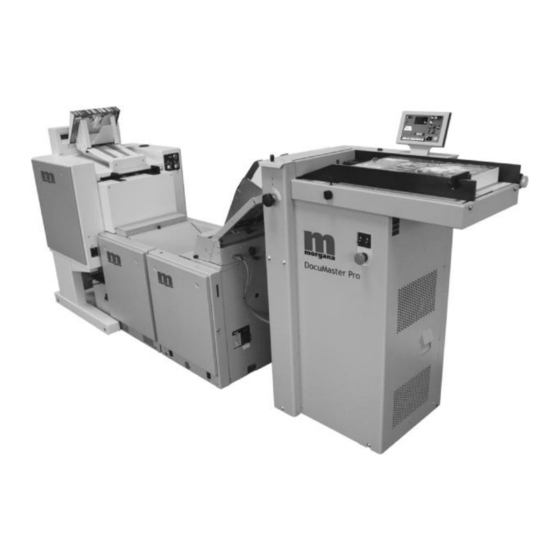
- Page 1 Documaster Pro DOCUMENT CREASING & AUTOMATIC BOOKLET MAKING MACHINE OPERATORS MANUAL (Part 2) (Booklet Making Unit) Morgana Systems Limited United Kingdom Telephone: ( 01908 ) 608888 Facsimile: ( 01908 ) 692399 Website: www.morgana.co.uk 2010 ISSUE 1 70-152...
-
Page 2: Table Of Contents
CONTENTS Specifications ........1 Introduction ........3 Booklet Making ........10 Edge & Corner Stapling ....14 Edge Stapling & Folding ....16 The Staple Heads ......18 Troubleshooting Chart ....22 Maintenance ........26 Appendices Connecting the TMP ......30 Staple Position Adjustment ....32 Sharpening the TMP Blade ....34 Conveyor Clamp Adjustment .... -
Page 3: Specifications
DocuMaster Pro SPECIFICATION Intended Use This product is intended to be used for the stapling, folding and trimming of materials as specified. Electrical Voltage 115V, 60 Hz or 230V, 50 Hz Single Phase (earthed supply required) Power 150VA exc. TRIM (115V) 500VA inc. - Page 4 Dimensions BookMaster Pro 546, 495, 595mm, 70kg (W,D,H) 21.5, 19.5, 23.4", 154.3lb BookMaster Pro with 546, 830*, 840mm**, 79kg Motorised Infeed (W,D,H) 21.5, 32.7, 33.1", 174.2lb TrimMaster Pro 546, 650, 595mm, 85kg (W,D,H) 21.5, 25.6, 23.4", 187.4lb † Outfeed Conveyor 404, 1050, 720mm , 17kg (W,D,H) 15.9, 41.3, 28.4", 37.5lb *Depth without paper tray is 710mm (28.0").
-
Page 5: Introduction
DocuMaster Pro INTRODUCTION The BookMaster Pro and TrimMaster Pro have been designed to staple, fold and trim booklets of up to 20 sheets, in a wide range of paper sizes. Their modular design means that they are equally at home being used offline, or online with a Watkiss Collator. - Page 6 The instructions that follow include the set-up and operating procedure for the BookMaster Pro, the Trim- Master Pro and the Motorised Infeed units. Please ignore those parts of the instructions that do not apply to your configuration. In these instructions the BookMaster Pro is referred to as the BMP and the TrimMaster Pro is referred to as the TMP.
- Page 7 DocuMaster Pro SWITCHING ON Plug in the BMP unit to a single phase power supply of the correct voltage as indicated by the mains input (see Figure 5). Mains ON/OFF Switch Voltage Indicator Label Mains Input FIGURE 5 Also ensure the outfeed conveyor cable is connected to the socket on the BMP (see Figure 6).
- Page 8 An alternative is the BookMaster Infeed Guide, P/N 041-572 (see Figure 4) Sidelay Paper Tray Motorised Infeed P/N 041-571 FIGURE 7 Fitting the Motorised Infeed Loosen the two hand screws (see Figure 8) on either side of the Motorised Infeed. Fixing Clip Hand Screw FIGURE 8...
- Page 9 DocuMaster Pro Connect the Motorised Infeed interface cable to the socket on the top of the BMP (see Figure 9). Motorised Infeed Socket FIGURE 9 Position the Motorised Infeed on the BMP, so that the fixing clips (see Figure 8) locate inside the BMP infeed.
- Page 10 The BMP will automatically start when a set of sheets is fed into the Motorised Infeed. The BMP will automatically stop approximately 10 seconds after the last feed, and return to the standby mode. The Motorised Infeed will only feed the next set when the BMP is ready.
- Page 11 DocuMaster Pro THIS PAGE IS INTENTIONALLY BLANK SYSTEM Page 9...
-
Page 12: Booklet Making
BOOKLET MAKING SETTING UP THE Select Centre Stapling BMP & TMP Using the lever on the BMP (see Figure 16), select centre staple operation (lift up). Edge or Centre Staple Selection Staple Head Selection Staple Head Staple Selection Centre Head Indicator Staple Select... - Page 13 DocuMaster Pro Fold Roller Adjustment Lever FIGURE 17 The lever has 11 positions. To move the fold rollers further apart (i.e. for larger sets or thicker stock) move the lever upwards. Move the lever down to bring the fold rollers closer together.
- Page 14 The contact point of the wheels should be aligned with the required dimension on the scale, as shown by the dotted line in the photo (see Figure 18). If required, make any fine adjustments once the job is running. Tip: Common sizes are highlighted on the scale.
- Page 15 DocuMaster Pro THIS PAGE IS INTENTIONALLY BLANK SYSTEM Page 13...
-
Page 16: Edge & Corner Stapling
EDGE & CORNER STAPLING Corner stapling is only possible if an optional third staple head is fitted (see Figure 20). Optional Third Staple Head for Corner Stapling FIGURE 20 ORGANISING THE Loading the Motorised Infeed The staples will be inserted into the feed edge of the set. The sheets should therefore be loaded accordingly, i.e feed the set spine-first into the unit. - Page 17 DocuMaster Pro Edge or Centre Staple Selection Staple Head Selection Staple Head Staple Selection Centre Head Indicator Staple Select Light Edge Staple FIGURE 21 Adjust the Staple Heads If required, open the BMP lid and adjust the position of the staple heads via the lever (see Figure 24 on p.26).
-
Page 18: Edge Stapling & Folding
EDGE STAPLING & FOLDING If required, it is also possible to edge staple the set and then fold it. The only limitation to this is that the distance from the stapled edge to the fold must be at least half the width of the paper. - Page 19 DocuMaster Pro THIS PAGE IS INTENTIONALLY BLANK SYSTEM Page 17...
-
Page 20: The Staple Heads
THE STAPLE HEADS CHANGING THE When a staple cartridge runs out, the corresponding red STAPLE CARTRIDGES indicator light (see Figure 22) will blink once per second. New cartridges are available (P/N 810-022). To change a cartridge, first open the BMP lid by turning the handle to the left and lifting (see Figure 22). - Page 21 DocuMaster Pro Fit the new cartridge and check the machine operation by making a few test booklets. ADJUSTING THE The staple heads have two positions. Normally the heads POSITION OF THE should be in the outer position (138mm, 5.4" between STAPLE HEADS staple centres).
- Page 22 Note: You may have to increase the infeed sidelay gap to access the hand screws. To do this, increase the paper width on the Creaser unit. Before placing your hands inside the BMP, you should disconnect the unit from the mains electricity supply. To close the BMP lid, lift it slightly, push the support strut (see Figure 26) and close the lid.
- Page 23 DocuMaster Pro THIS PAGE IS INTENTIONALLY BLANK SYSTEM Page 21...
-
Page 24: Troubleshooting Chart
TROUBLESHOOTING CHART The following is a guideline to help solve any problems or errors, if they persist please call the Morgana Service Department or your Morgana Dealer. PROBLEM CAUSE SOLUTION Operational Problems BMP WILL NOT START The BMP is not plugged in Plug into mains connection of the correct type and voltage. - Page 25 DocuMaster Pro PROBLEM CAUSE SOLUTION STAPLE IS NOT ON THE FOLD Loose paper or staples in the fold Locate and remove (see p. 24) plate area. The infeed sidelays are set too tight Adjust so that the infeed sidelays barely touch the paper...
- Page 26 PROBLEM CAUSE SOLUTION BOOKLETS ARE TRIMMED TMP conveyor clamp requires See Appendix 4 TOO SHORT adjustment COVER IS DAMAGED TMP conveyor clamp requires See Appendix 4 AROUND STAPLES adjustment Fold roller gap is too narrow Adjust the fold roller gap (see p. 10) Staple Head Problems ONE OR BOTH LEGS TURN Incorrect clincher alignment...
- Page 27 DocuMaster Pro THIS PAGE IS INTENTIONALLY BLANK SYSTEM Page 25...
-
Page 28: Maintenance
MAINTENANCE The BMP and TMP units require only a small amount of routine maintenance. CLEANING Build up of set-off powder, ink or general dust will grad- ually impair the performance of your BMP and TMP. Optimum performance will be obtained by keeping the machine clean. - Page 29 DocuMaster Pro and belts with a cloth dampened with soap and water or alcohol (isopropanol). Do NOT use blanket wash. Manual Cranking Point FIGURE 28 To clean the belts on the TMP, first remove the left hand side cover (two x M5 button screws) to give access to the manual cranking point (see Figure 29).
- Page 30 Open the TMP conveyor lid (see Figure 29) by lifting the orange hand screw (this doesn’t need to be loosened, just use it as a handle). Manual Cranking Point FIGURE 30 Using a 19mm A/F spanner (wrench), manually crank the TMP by turning the nut (see Figure 30) clockwise, and clean the belts with a cloth dampened with soap and water or alcohol (isopropanol).
- Page 31 DocuMaster Pro THIS PAGE IS INTENTIONALLY BLANK SYSTEM Page 29...
-
Page 32: Connecting The Tmp
CONNECTING THE TMP Procedure Open the BMP lid by turning the handle to the left and lifting (see Figure 31). The lid is supported by a strut on the right side. FIGURE 31 Line up the TMP docking plates (see Figure 32) with the BMP. - Page 33 DocuMaster Pro Push the two units together so that the hooks on the TMP docking plates align with the holes in the BMP side plates (see Figure 33). FIGURE 33 Lift the BMP lid slightly, push the support strut (see Figure 34) and close the lid.
-
Page 34: Staple Position Adjustment
STAPLE POSITION ADJUSTMENT Tools required If both staples are consistently off the spine of the book Flat Blade Screwdriver first ensure that the BMP is adjusted correctly and that delivery into the unit is good. If the problem persists, fine tuning of the staple position may be necessary. - Page 35 DocuMaster Pro THIS PAGE IS INTENTIONALLY BLANK SYSTEM Page 33...
-
Page 36: Sharpening The Tmp Blade
SHARPENING THE TMP BLADE The TMP blade and anvil are located behind the conveyor assembly (see Figure 37) at the docking end of the unit. Conveyor Cover Conveyor Assembly FIGURE 37 Periodically all TMP blades will require re-grinding. Poor grinding will result in poor life, and can cause cracks and nicks in the blade. - Page 37 DocuMaster Pro Procedure Separate the TMP from the BMP. Open the TMP conveyor cover (loosen the orange hand nut). Remove the two orange hand screws that secure the conveyor assembly to the TMP unit (see Figure 38). Orange Hand Screws...
- Page 38 Removing the TMP Blade Slightly loosen all five blade fixing screws (see Figure 40). Remove the outer two screws and screw them into the locator holes. These will now act as handles. Remove the remaining screws and carefully lift the blade away. Immediately put the blade away safely.
- Page 39 DocuMaster Pro Manual Crank Drive Access Hole FIGURE 41 Remove the left hand TMP side cover (two x M5 but- ton screws and washers). Release the clutch by de- pressing the lever (see ar- ow) through the access hole in the side plate (see Figure 41).
- Page 40 Final adjustment Release the clutch and manually crank slowly several rotations to check that the blade passes the anvil smoothly without obstruction. Place a single sheet of paper (large sheet size) between the blade and the anvil and manually crank to produce a test cut.
- Page 41 DocuMaster Pro TrimMaster Blade Grinding Instructions TrimMaster blade 253-835 is fitted with a Note: guide leg. This be removed when the BLADE ANVIL must blade is reground and refitted afterwards. Note: Note. 2 faces must 2 faces must be flat to within...
-
Page 42: Conveyor Clamp Adjustment
CONVEYOR CLAMP ADJUSTMENT The TMP conveyor clamps are set to a default position at the factory, which gives a good trim over a wide variety of booklet thicknesses. However, when trimming unusually thick or thin booklets, the conveyor clamps may need to be adjusted. If the conveyor clamps are set too loose, the booklet may not be delivered correctly to the trim stop, or it may bounce... - Page 43 DocuMaster Pro Open the TMP conveyor cover, by lifting the orange handscrew (see Figure 43). Conveyor cover FIGURE 43 There are two clamp roller shafts, which are adjusted using a 4mm allen key (see Figure 44). Adjustment Adjustment screw screw...
- Page 44 Checking the adjustments It is important that both clamp roller shafts are adjusted to the same height. The factory default is 17mm between the top of each shaft and the top of the wire frame. When making any adjustments, you must re-measure the height of both shafts, to ensure they are set the same.
- Page 45 DocuMaster Pro THIS PAGE IS INTENTIONALLY BLANK SYSTEM Page 43...
-
Page 46: Index
INDEX adjustable fold rollers 10 paper jams 24 adjustment of conveyor clamp 40–42 payout wheels adjustment 11 power supply 1 blade sharpening, tmp 28 booklet making 10–12 radio frequency emissions 2 setting up the bmp 10-12 safety 4 centre staple selection 10 setting up the bmp 10–12 clamp roller shafts 41, 42 centre staple selection 10... - Page 47 DocuMaster Pro SYSTEM Page 45...
Need help?
Do you have a question about the Documaster Pro and is the answer not in the manual?
Questions and answers