Table of Contents
Advertisement
Quick Links
Advertisement
Table of Contents

Related Manuals for Minuteman E26


Summary of Contents for Minuteman E26
- Page 1 User Manual Minuteman,Inc. A member Of The Hako Group 988026UM REV A 06/2022...
- Page 2 Introduction Preface Valid as of: November 2011 Dear customer, It is our desire that the good characteristics of the E26 Minuteman International,Inc. should justify the confi dence you demonstrated by 14N845 US Route 20 making this purchase. Prior to the fi rst operation, carefully Pingree Grove, Illinois 60140 read the chapter “Safety Information”...
- Page 3 The maintenance work has to be performed by an authorized along with waybill to: Minuteman service center and confi rmed in the “Maintenance Certifi cate” which is the warranty document. Minuteman International,Inc.
-
Page 4: Table Of Contents
Table of Contents 3.1.2 Clean Water Tank............12 3.1.3 Squeegee ..............13 1 Safety information ............6 3.1.4 Dirty Water Recovery Tank ..........13 3.1.5 Drive System..............13 1.1 Safety and Warning Symbols ..........6 3.1.6 Batteries and Charger ..........13 1.2 General Provisions ...............6 3.1.7 Options ................13 1.3 Provisions for Operation ............7 3.2 Control Panel &... - Page 5 5.5.3 Cleaning Clear Water Filter ........29 5.6.1 Empty Recovery Tank ..........31 5.6.2 Cleaning the Recovery Tank ........31 5.6.3 Clean Suction Filter............31 5.7 Scrub Head .................32 5.7.1 Cleaning Brushes ............32 5.7.2 Changing Brushes ............32 5.7.3 Changing Defl ector Roller ...........32 5.7.4 Changing Scrub Head Skirt ........32 5.8 Squeegee ................33 5.8.1 Cleaning the Squeegee ..........33 5.8.2 Changing the Squeegee Blades........33...
-
Page 6: Safety Information
Indicates a hazardous situation • Only persons trained by qualifi ed Warning Persons and Goods which could result in death or Minuteman personnel are authorized serious injury. to operate, service and repair the machine. Indicates important or additional Note •... -
Page 7: Provisions For Operation
(doorsteps). well as with those of the battery maintenance and repair work • Empty dirty water tank before folding manufacturer. Minuteman cannot beyond this please contact your local recovery tank over. be held liable for damages Minuteman service center. -
Page 8: Specifi C Hazards
• Have the machine checked for equipment. Battery safety conditions in the sense • The use of aggressive detergents is • Follow the operating instructions of the of the Accident Prevention not recommended. battery manufacturer. Regulation by an expert at regular •... -
Page 9: Labels On The Machine
C = Do not clean the machine by means immediately. of high-pressure cleaning equipment (Fig. 1/2) Minuteman Decal (Fig. 1/1) Machine identifi cation number (Fig. 1/2) Dirty water drain hose (Fig. 1/3) Infl ation Pressure (Fig. 1/4) = 65 psi Fig.1... -
Page 10: First Operation
Use the following qualifi ed 2. Install brushes and squeegee, see procedure reset the machine into operating person sent by your local Minuteman maintenance chapter. mode: dealer. Your Minuteman dealer will be 3. Install batteries and connect battery •... -
Page 11: Stopping The Machine
Observe the legal directives 2.9 Tie Down Points Start moving machine and local regulations for disposal When transporting unit on a vehicle or immediately after lowering of detergents, see Water trailer, the scrub head,otherwise the Management Act. the machine must be protected against brushes may leave traces on 4. -
Page 12: Operation
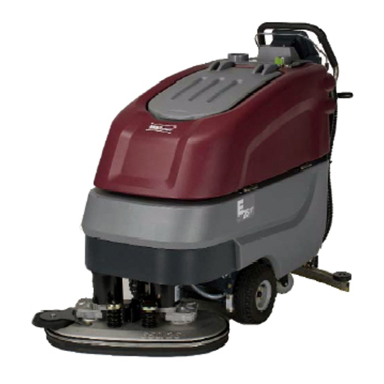
3 Operation 3.1 Method Of Operation General The E26 is a vacuum scrubbing machine for wet cleaning of hard surfaced fl oors. 3.1.1 Scrub Head Assembly Lower the scrub head assembly (Fig. 3/1) via pedal before scrubbing. The brushes will rotate and the water supply turns on automatically. -
Page 13: Squeegee
(Fig. 3/4) by a vacuum motor pad holder with centerlock and squeegee and suction hose. For cleaning and blades are available. Contact your Minuteman collecting water in places where Dealer for more information access is diffi cult, the machine is equipped with a handheld suction hose. -
Page 14: Control Panel & Operation Indicators
3.2 Control Panel & Operation Indicators 3.2.1 Operating Panel Display Key Switch Battery Charge Indicator LDS Indicator Symbol for Brush Drive Symbol for Vacuum Motor Hour Meter Symbol for Service Indicator Drive Direction Control (9a) with speed control knob (9b)and bail handle (9c) Page 14 Fig.4... - Page 15 Display (Fig. 4/1) LDS Indicator (Fig. 4/4) This panel allows centralized monitoring Upon switching on, the LDS indicator is of functions and status of all illuminated on the panel to show the current available operating modes. battery charge condition during operation. For additional Information see chapter on Service Indicator (Fig.
-
Page 16: At The Machine
3.2.2 At The Machine Brush deck pedal Opening of solution tank Solution control Sqeegee lever Solution tank fi lter Recovery tank drain hose Solution tank drain hose (Solution level indicator) Brush ejector Power Cord For Charger Fig.5 Page 16... - Page 17 Brush deck pedal (Fig. 5/1) Power cord for charger (Fig. 5/9) Use this pedal to lift and lower the brush deck. The pwer cord supplies the charger unit with power. Opening of solution tank (Fig.5/2) The solution tank is fi lled after folding up the opening. Solution control (Fig.
-
Page 18: Technical Data
4 Technical Data Machine length 59.5 in / 151 cm Machine height 43.7 in / 111 cm Machine width without Squeegee 26.8 in / 68 cm Machine width with squeegee 37.5 in / 95 cm Working width 25.6 in / 65 cm Squeegee width 37.5 in / 95 cm Surface performance theoretical... - Page 19 Noise emission The sound pressure level measured under maximum conditions of use (LwA) according dB(A) 82 to DIN EN 60335-2-72 amounts to: The sound pressure level measured (at the ear of the driver) under normal conditions dB(A) 67 of use (LpA) according to DIN EN 60335-2-72 amounts to: Measurement inaccuracy (KpA): dB(A) 1.6 Vibration...
-
Page 20: Maintenance And Care
The Minuteman System Maintenance: To be performed by qualifi ed personnel 5.1 General • Guarantees reliable operability of the of an authorized Minuteman Service Center Before performing Minuteman machines (Preventive in accordance with the machine-specifi c maintenance you are maintenance) -
Page 21: Maintenance Document
5.2 Maintenance Document Handing over System Maintenance II System Maintenance I System Maintenance I 250 operating hours 125 operating hours 375 operating hours Upgrade Workshop stamp Workshop stamp Workshop stamp Test drive Handing over to the customer Insttuction carried out on: carried out on: carried out on: carried out on:... -
Page 22: Maintenance Schedule
5.3 Maintenance Schedule System Maintenance K (performed by the Customer) The daily and weekly maintenance intervals are to be performed by the customer / operator. Interval To Be Performed Daily Weekly Fill solution tank and proceed to chemical agent dosage Charge batteries Check scrub head and clean if required Check squeegee and clean if required... - Page 23 System Maintenance I The following maintenance works are to be performed by an authorized Minuteman Service workshop. Interval To be performed Every 125 hours of operation Check battery charger Check tank lid seal of the recovery tank and replace if required...
- Page 24 System Maintenance II The following maintenance works are to be performed by an authorized Minuteman Service workshop. Interval To Be Performed Every 250 hours of operation Perform maintenance according to System Maintenance I Inspect steering rollers for tread damage and bearing slackness and replace if required...
- Page 25 System Maintenance S (Safety check) The following maintenance works are to be performed by an authorized Minuteman Service workshop at least once yearly. Interval To be Performed Every 500 hours of operation Perform maintenance work according to System Maintenance II...
-
Page 26: Battery Systems
5.4 Battery Systems LDS Display Charger Indicator Charger AC Power Cord for Charger Battery Connector Batteries Recovery Tank Support Wiring Diagram The handling and changing of batteries by qualifi ed persons only! Fig.7 Page 26... -
Page 27: Charging The Batteries
5.4.3 Removing Batteries before starting the machine and grease poles. Park machine on level ground. for the fi rst time. Minuteman Switch off machine by key switch. cannot be held liable for Open empty dirty water tank (Fig.7/7) 5.4.5 Disposal of Batteries battery damage resulting and secure with support (Fig. -
Page 28: Solution Tank
5.5 Solution Tank Clean Water Solution Tank Solution Full Marker Fill Level Hose Clean Water Filter Solution Tank Lid Fig.8 Page 28... -
Page 29: Filling The Solution Tank
5.5.1 Filling the Solution Tank 5.5.3 Cleaning Clear Water Filter Fill solution tank (Fig. 8/1) before operation or as required. Check clean water fi lter (Fig. 8/4) at weekly intervals. Clean Park vehicle on level ground. Open tank lid (Fig. 8/5) or replace if required. - Page 30 5.6 Dirty Water Recovery Tank 1 Dirty Water Recovery Tank 2 Recovery Tank Drain Hose 3 Suction Filter 4 Recovery Tank Lid Fig.9 Page 30...
-
Page 31: Empty Recovery Tank
5.6.1 Empty Recovery Tank 5.6.2 Cleaning the Recovery Tank Clean recovery tank (Fig. 9/1) at daily intervals, as required Clean the recovery tank (Fig. 9/1) at daily intervals or as or upon acoustic signal (increased suction motor speed). required. Take machine to appropriate place for discharge. Empty recovery tank, see paragraph 5.6.1. -
Page 32: Scrub Head
5.7 Scrub Head 5.7.1 Cleaning Brushes 5.7.2 Changing Brushes 1 Pedal for Scrub Head Lift Clean scrub brushes (Fig.10/2) at daily intervals Check brushes for wear at weekly intervals. 2 Scrub Head or as required. Replace brushes if bristles are worn down to a 3 Brush Ejectors length of 1.5 cm. -
Page 33: Squeegee
5.8 Squeegee 5.8.1 Cleaning the Squeegee 5.8.2 Changing the Squeegee Blades Check the squeegee (Fig. 11/1) daily Check the inner and outer squeegee 1 Squeegee and clean as necessary. blades on the squeegee (Fig. 11/1) weekly 2 Star-shaped knob To clean it lift the squeegee out, pull for signs of wear. -
Page 34: Adjusting The Blades Angle Adjustment
5.8.3 Adjusting the Blades Angle Adjustment The angle adjustment is the decisive factor in ensuring that the squeegee blades on the squeegee lie evenly on the fl oor. Park the machine on a level surface and lower the squeegee. Loosen the counternut on the adjusting screw (Fig. - Page 35 Height Adjustment The height adjustment is set to 3mm at the factory. If streaks are produced, despite an optimum angle adjustment, the clearance between the casters and fl oor must be adjusted by changing the number of washers on the holder.
- Page 36 “More Than Just Clean” Minuteman is a Full Line Manufacturer of Sweepers and Scrubbers, for Industrial Facilities. Minuteman,Inc. A member Of The Hako Group 988026UM REV A 06/2022...
Need help?
Do you have a question about the E26 and is the answer not in the manual?
Questions and answers