Table of Contents
Advertisement
Quick Links
Advertisement
Table of Contents

Related Manuals for Minuteman E17


Summary of Contents for Minuteman E17
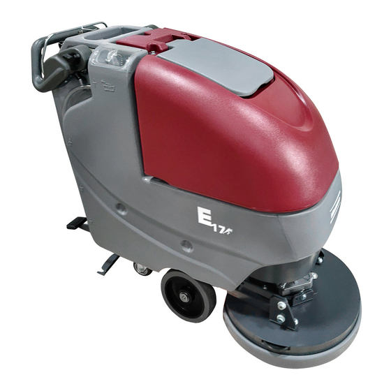
- Page 1 Parts and Instruction Manual E17/E20 Scrubber...
- Page 2 This manual is furnished with each new MINUTEMAN E17/E20. This provides the necessary operating and preventive maintenance instructions. Operators must read and understand this manual before operating or servicing this machine. This machine was designed to give you excellent performance and efficiency. For best results and minimal cost, please follow the general guidelines below: •...
-
Page 3: Table Of Contents
Solution Fill Filter ..........................9 Brush Load / Unload ........................10 Loading Brush ..........................10 Unloading Brush ..........................10 Screened Float ..........................11 Screened Float Removal ........................11 The E17/E20 ............................12 Machine Operation ........................... 13 Parts and Instruction Manual... - Page 4 20” Brush Deck Assembly BOM ....................37 E17 Brush Hub Assembly ......................38 E20 Brush Hub Assembly ......................39 Rear Squeegee Assembly ......................40 Squeegee Mechanism Assembly ....................41 Wiring Diagrams ..........................42 Minuteman International Made Simple Commercial Limited Warranty ........45 Parts and Instruction Manual...
-
Page 5: Important Safety Instructions
Do not operate this machine in flammable or explosive areas. This machine is designed solely for scrubbing dirt and dust in an indoor environment. Minuteman does not recommend using this machine in any other capacity. The following information below may cause a potential hazard to the operator and equipment. -
Page 6: Inspection & Unpacking
Inspection & Unpacking Carefully unpack and inspect your E17/E20 Walk-Behind Scrubber for shipping damage. Follow unpacking instructions on shipping pallet. Each unit has been tested and thoroughly inspected before shipment. Any damage is the responsibility of the delivery carrier who should be notified immediately. -
Page 7: Machine Overview
Machine Overview - Front CUP HOLDER SOLUTION FILL PORT RECOVERY TANK LID RECOVERY TANK BRUSH DECK FRONT WHEEL REAR CASTER SOLUTION TANK Machine Overview - Rear BAIL HANDLE RECOVERY HOSE SQUEEGEE LIFT LEVER CONTROL PANEL SOLUTION CONTROL LEVER SOLUTION TANK DRAIN HOSE / LEVEL INDICATOR RECOVERY TANK DRAIN HOSE BRUSH LIFT PEDAL ONBOARD CHARGER CORD... -
Page 8: Control Panel
Machine Overview - Control Panel BAIL HANDLE HANDLE ADJUSTMENT KNOB KEY SWITCH SQUEEGEE LIFT LEVER SOLUTION CONTROL LEVER BATTERY GAUGE CHARGE STATUS INDICATOR The Control Panel For operator ergonomics, the control panel houses all the primary functions. Controls are grouped in a central area at the rear of the machine. -
Page 9: Optional Hour Meter
Optional Hour Meter Minuteman offers an optional hour meter for the E17/E20. The optional kit replaces the power cord mounting bracket at the rear of the machine with one that contains an hour meter. Kit# K-E1720HM Optional Solution Solenoid Minuteman offers an optional solution solenoid for the E17/E20. The optional solenoid automatically turns off the solution flow when the brush motor is not active. -
Page 10: Circuit Breakers
12-volt batteries connected in series. Connect the batteries according to the battery con- nection diagram (see diagram). The recommended batteries are 105Ah (Minuteman P/N 956712) or 100Ah (minuteman P/N 956100) Gel. The battery tray may be drained if neccessary using the or- ange drain hose located above the rear caster on the right side of the machine. -
Page 11: Rear Squeegee
Rear Squeegee The rear squeegee is the main element of the conduit that transfers the spent solution into the recovery tank. A daily maintenance check of this component is essential to have optimum machine performance. The blade configuration has two usable edges and can be turned inside out to utilize the opposite side of the blade. -
Page 12: Handle Adjustment
Handle Adjustment The E17/E20 handle was designed with operator comfort in mind. The angle and horizontal position of the handle can be adjusted to suit the needs of the operator. Angle Adjustment The handle angle can be adjusted without tools by loosening the angle adjustment knob (A) on each side and rotating the handle to the desired position. -
Page 13: Solution Tank Drain Hose / Level Indicator
Solution Tank Drain Hose / Level Indicator Solution Tank Drain Hose The solution tank may be drained by removing the Solution Tank Drain Hose (A) from the Hose Barb (B) and routing the hose to a floor drain. Solution Level Indicator The Solution Tank Drain Hose also serves as a water level indicator for the solution tank. -
Page 14: Brush Load / Unload
Lower the scrub deck by To load the brush, first center bail handle to spin the scrub releasing the deck lift pedal. the E17/E20 brush deck over brush onto the scrubdeck. the scrub brush. Unloading Brush Momentarily (1 to 2 seconds) -
Page 15: Screened Float Removal
Screened Float If the recovery tank (C) is overfilled or a large amount of foaming is present, the screened float (B) blocks the vacuum intake inside the tank protecting the vacuum motor and internal electronics from water damage. It is essential to keep the float in working order through regular maintenance. -
Page 16: The E17/E20
This machine was designed with total operator comfort and ease of use in mind. All machine components have been designed as a total system to efficiently clean dirty floors. The E17/E20 has two available scrub head types and sizes to fit specific applications. Please contact your Minuteman representative for specific recommendations for the correct scrub head type, size, and brush type and chemical applications. -
Page 17: Machine Operation
Machine Operation To Turn on Machine: Turn key to operate position ( I ) To Turn on Vacuum: Lower squeegee into operate position, vacuum motor will turn on automatically. To Turn on Brush Motor: Move brush lift pedal from the “home” (down) position to the operating position (up). Depress the operator bail handle. -
Page 18: After Use
After Use When finished scrubbing, lift the scrub deck and turn the solution lever off, water flow will cease. Lift the rear squeegee (the vacuum motor will turn off). Move the machine to a service area for daily maintenance and review items that may need service. -
Page 19: General Machine Troubleshooting
Reconnect or replace recovery hose tank disconnected or damaged Worn brushes Rotate or replace brushes Poor scrubbing performance Wrong brush or cleaning chemical Consult Minuteman Debris caught on scrub brushes Remove debris Moving machine too fast Slow down Not using enough solution... -
Page 20: Exploded Views
Exploded Views Main Assembly Parts and Instruction Manual Page 16... -
Page 21: Main Assembly Bom
NUT-FLANGED WIZZ 10-24 715917 DECAL, E17 715920 DECAL, E20 740164-1 JUMPER CABLE ASSY, RED 4G 12" 747649 CABLE ASSY, BATTERY E17 956712 BATTERY, 12V 105 AH 956100 GEL BATTERY 12V 100AH 172001BD-120 BRUSH DRV BASE ASSY-120V CHARGER 21CE 172001BD-230 BRUSH DRV BASE ASSY-230V CHARGER... -
Page 22: Brush Drive Base Assembly
Brush Drive Base Assembly Parts and Instruction Manual Page 18... -
Page 23: Brush Drive Base Assembly Bom
Brush Drive Base Assembly BOM BILL OF MATERIAL - 172001BD-120/230 ITEM PART NO. REQ'D DESCRIPTION 172002 BD CHASSIS ASSY, ES1720 172012 BATTERY TRAY ASSY 172016 E1720 BD HANDLE ASSY 172032 LIFT PEDAL WMT 172050 VAC MOTOR ASSY 172055 BKT, VAC AREA INSIDE COVER 172070-120 ELEC BOX BD ASSY 120V 172070-230... -
Page 24: E17/20 Base Assembly
E17/20 Base Assembly BILL OF MATERIAL - 172001BASE ITEM PART NO. REQ'D DESCRIPTION 172013 SOL TANK ASSY, ES1720 172014 REC TANK ASSY 172144 PANEL, FRONT 1720 711504 WSR-FLAT 1/4 ID SS 711543 WSR-HELICAL #10 712041 BLT- SHLDR 1/4-20 X .44 X .37 712312 WSR-FLAT .187 X 1.25... -
Page 25: Chassis Assembly
Chassis Assembly Parts and Instruction Manual Page 21... -
Page 26: Chassis Assembly Bom
Chassis Assembly BOM BILL OF MATERIAL - 172002 ITEM PART NO. REQ'D DESCRIPTION 70-516-16 BLT-CAR 5/16-18 X 1.00 172020 MAIN FRAME WMNT, ES1720 172024 WHEEL BRACKET, ES1720 172025 DECK LIFT ASSY 172030 BAR, UPPER DECK LIFT W/ BUSH 172035 WHEEL ROD, ES1720 172038 BEARING BLOCK 172039... -
Page 27: Solution Valve Assembly
Solution Valve Assembly BILL OF MATERIAL - 172064 ITEM PART NO. REQ'D DESCRIPTION 172063 BKT, SOL VALVE MOUNT 172158 HOSE, 1/2"ID X 7.5" NYLOBRAID 320265 FITTING DUBL 3/8HBx3/8MPT 383347 CRIMP CLAMP 1/2 HOSE SS 185R 711512 WSR-FLAT .75X1.37X.08 711513 WSR-FLAT .69 X 1.06 X .03 SS 809415 VALVE, 3/8 FPT, 45 OPEN/CLOSE 827008... -
Page 28: Solution Tank Assembly
Solution Tank Assembly BILL OF MATERIAL - 172013 ITEM PART NO. REQ'D DESCRIPTION 172003 SOLUTION TANK, ES1720 172080 HANDLE MOUNT ASSY, LEFT 172082 HANDLE MOUNT ASSY, RIGHT 260579 TOOL CLIP, 1.5" HOSE 342438 FITTING, 1/2 MPT 1/2 HB BRASS 711507 WSR-FLAT .37 X 1.12 X .06 711546 WSR-HELICAL 3/8... -
Page 29: Lift Pedal Stop Assembly
Lift Pedal Stop Assembly BILL OF MATERIAL - 172157 ITEM PART NO. REQ'D DESCRIPTION 172036 BKT, PEDAL STOP 172065 CLIP, FOR 1/2" ID HOSE 710493 SCR-MC 4-40 X .75 PAN HD 710530 SCR-MC FL HD 8-32 X .50 BRS 711428 NUT-HEX 4-40 712326 WSR-INT LOCK #4... -
Page 30: Recovery Tank Assembly
Recovery Tank Assembly Parts and Instruction Manual Page 26... -
Page 31: Recovery Tank Assembly Bom
Recovery Tank Assembly BOM BILL OF MATERIAL - 172014 ITEM PART NO. REQ'D DESCRIPTION 172004 ES1720 RECOVERY TANK 172005 ES1720 VACUUM MANIFOLD 172007 ES1720 LID 172011 HOSE, PINCH-OFF W/ CAP, 36" 172017 GASKET, LID 172049 HINGE, RECOVERY TANK 172067 REC TANK CABLE ASSY 11.625 172132 SCREENED FLOAT 260203... -
Page 32: Handle Assembly
Handle Assembly BILL O F M ATERIAL - 172016 IT EM P ART NO . REQ'D DES CRIP TIO N 172006 E S 1720 HA NDLE 172053 B A IL P LA TE W M T RH 172054 B A IL P LA TE W M T LH 172057 E S 1720 LE A F S P RING 172059... -
Page 33: Battery Tray Assembly
Battery Tray Assembly BILL OF MATERIAL - 172012 ITEM PART NO. REQ'D DESCRIPTION 172116 ES1720 BATTERY BOX 260224 18" HOSE 320271 NOZZLE BODY-ELBOW 320272 NOZZLE BODY LOCKNUT 320273 HOSE SHUT-OFF CLAMP 828490 CRIMP CLAMP 140R Parts and Instruction Manual Page 29... -
Page 34: Electrical Box Assembly
Electrical Box Assembly Parts and Instruction Manual Page 30... -
Page 35: Electrical Box Assembly Bom
Electrical Box Assembly BOM BILL OF MATERIAL - 172070-120/230 ITEM PART NO. REQ'D DESCRIPTION 172077 ELEC BOX-BOT HALF WMT 172088 ELEC BOX-TOP HALF WMT 172107 BKT, UPPER BUSHING MOUNT 172128 BKT, LOWER BUSHING MOUNT 172141 VAC SWITCH ASSY 172149 CABLE ASSY, SQUEEGEE LIFT 172152 VAC LEVER WMT 172188... -
Page 36: Electrical Box Cover Assembly
Electrical Box Cover Assembly BILL OF MATERIAL - 172073 ITEM PART NO. REQ'D DESCRIPTION 172181 ELEC BOX, COVER, WMT 715672 DECAL, 1720 BD ELEC BOX 715673 DECAL, 1720 BD DASHBOARD 715675 DECAL, BD CIRC BKRS 740216 VOLT METER 747614 CHARGE STATUS INDICATOR 747617-1 KEYSWITCH ASY, KEYSWITCH + WIR Parts and Instruction Manual... -
Page 37: Vac Motor Assembly
Vac Motor Assembly B I L L O F M A T E R IA L - 1 7 2 0 5 0 I T E M P A R T N O . R E Q 'D D E S C R I P T I O N 1 7 2 0 4 5 V A C M O U N T W M T, E S 1 7 2 0 1 7 2 0 4 8... -
Page 38: 17" Brush Deck Assembly
17” Brush Deck Assembly Parts and Instruction Manual Page 34... -
Page 39: 17" Brush Deck Assembly Bom
DECK COVER WMT 17" 172118 17" DECK SKIRT 172119 RETAINER, 17" DECK SKIRT 172154 HOSE-NYLO REINF 3/8 X 27" 172165 E17 BRUSH HUB ASSY 210153 ROLLER WHEEL 450076 CRIMP CLAMP SS 185R 710985 SCR-SC 3/8-16 X .62 ST PL 711354... -
Page 40: 20" Brush Deck Assembly
20” Brush Deck Assembly Parts and Instruction Manual Page 36... -
Page 41: 20" Brush Deck Assembly Bom
20” Brush Deck Assembly BOM BILL OF MATERIAL - 172100 ITEM PART NO. REQ'D DESCRIPTION 172040 DECK ANGLE ADJUST WMT 172044 PLATE, MOTOR MOUNT 172095 E20 BRUSH HUB ASSY 172101 DECK COVER WMT 20" 172121 20" DECK SKIRT 172125 RETAINER, 20" DECK SKIRT 172153 HOSE-NYLO REINF 3/8 X 29"... -
Page 42: E17 Brush Hub Assembly
E17 Brush Hub Assembly BILL OF MATERIAL - 172165 ITEM PART NO. REQ'D DESCRIPTION 172133 BRUSH HUB SPACER 711554 WSR-INTERNAL LOCK 1/4 ID 717026 SCR-SC SHCS M6X1.0 X 25 STL Z 172096MCH BASE, DRIVE HUB WITH KEYWAY 172097MCH HUB, MACHINED FOR E17... -
Page 43: E20 Brush Hub Assembly
E20 Brush Hub Assembly BILL OF MATERIAL - 172095 ITEM PART NO. REQ'D DESCRIPTION 172097 ES1720 BRUSH HUB BASE 172133 BRUSH HUB SPACER 711554 WSR-INTERNAL LOCK 1/4 ID 717026 SCR-SC SHCS M6X1.0 X 25 STL Z 172096MCH BASE, DRIVE HUB WITH KEYWAY Parts and Instruction Manual Page 39... -
Page 44: Rear Squeegee Assembly
Rear Squeegee Assembly BILL OF MATERIAL ITEM PART NO. REQ'D DESCRIPTION 210023 SQUEEGEE CASTING ASY 210024 SQUEEGEE MOUNT BKT 210065 SQUEEGEE BLADE 200 GUM 430074 ADJUSTING NUT 17B/E 430076 NYLON SQUEEGEE INSERT 430085 SQUEEGEE BUMPER WHEEL 712517 SCR-MC 8-32 X 1" ST PL - PH 831400 WHEEL ASSY Parts and Instruction Manual... -
Page 45: Squeegee Mechanism Assembly
Squeegee Mechanism Assembly BILL OF MATERIAL - 172170 ITEM PART NO. REQ'D DESCRIPTION 172171 SQUEEGEE MECH WMT 172173 BKT, MAIN SQUEEGEE HINGE 172175 BKT, STANDOFF 260579 TOOL CLIP, 1.5" HOSE 430073 GASKET DIE CUT PS BACK 710530 SCR-MC FL HD 8-32 X .50 BRS 711504 WSR-FLAT 1/4 ID SS 711678... -
Page 46: Wiring Diagrams
Wiring Diagrams... -
Page 49: Minuteman International Made Simple Commercial Limited Warranty
A potential health hazard exits without original equipment replacement. All warranted items become the sole property of Minuteman or its original manufacturer, whichever the case may be. Minuteman disclaims any implied warranty, including the warranty of merchantability and the warranty of fitness for a particular purpose.
Need help?
Do you have a question about the E17 and is the answer not in the manual?
Questions and answers