Table of Contents
Advertisement
Quick Links
Advertisement
Table of Contents
Troubleshooting

Related Manuals for Phason AutoFlex Connect


Summary of Contents for Phason AutoFlex Connect
- Page 2 Copyright Phason Inc. Printed in Canada All rights reserved. 32943005...
-
Page 3: Table Of Contents
Connecting equipment to Feed Loop Kits ..................24 Connecting an alarm system ......................25 Connecting the power source ......................27 Finishing the installation .......................... 27 Chapter 4: Overview of AutoFlex Connect ............... 28 Getting started ............................28 Log in ..............................28 Go through the screens ........................28 Create users ............................ - Page 4 Appendixes ........................36 Appendix A: Troubleshooting ......................... 36 Appendix B: Calibrating and troubleshooting actuators................. 38 Calibrating actuators ........................... 38 Determining correct actuator feedback wiring ..................39 Appendix C: Additional modules and repair kits ..................40 Index ..........................43...
-
Page 5: Chapter 1: Introduction
AutoFlex Connect brings flexibility and versatility to your fingertips. AutoFlex controls provide an intuitive touchscreen interface at the control. Not at the control? No problem. AutoFlex Connect is accessible from any web-enabled device. No matter where you are, your AutoFlex Connect controls are always within reach. -
Page 6: Available Modules
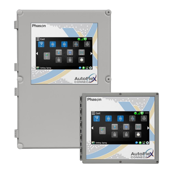
Introducing AutoFlex Connect AutoFlex controls are available in two models: AutoFlex Connect AutoFlex Connect Mini Room for 14 modules Room for 6 modules NEMA 4X enclosure (22 x 15 x 7 in.) NEMA 4X enclosure (11 x 11.85 x 3.95 in.) 11.85 in. - Page 7 For installation information, read Connecting equipment to Variable AC on page 21. Modules For information about Single-Phase Slave units, visit www.phason.ca (model Variable Chimney Module VCM-DC The Variable Chimney Module has two DC-signal outputs (0 to 10 V) for controlling a chimney fan and damper. There is also an input for connecting a measuring fan.
-
Page 8: Chapter 2: Installation
Surge suppression devices offer some protection from power surges. Because it is not possible to internally protect this product completely from the effects of power surges and other transients, Phason highly recommends that you install external surge suppression devices. For specific recommendations, see your electrical contractor. If you do not take these precautions, you... -
Page 9: Reducing Electrical Noise Using Filters
Phason’s snubber filters (part number 127-0) are for use with solenoids, timer relays, DC motors, furnaces, and other equipment connected to the control’s relays. You can also use the filters with loads connected to power contactors. -
Page 10: Electrical Ratings
0.2 A at 125 VAC; 1 A at 30 VDC, inductive load Using power contactors to increase the capacity of relays Phason’s 240-volt power contactors are heavy-duty relays that allow you to increase the load handling capability of control relays. Power contactors are ideal for secondary ventilation fans and electric heaters. - Page 11 AutoFlex 12 in. (30.5 cm) 12 in. 12 in. 12 in. Mounting holes (x5) 14.9 in. (37.8 cm) 7.1 in. (18.0 cm) Mount high-voltage modules (Relay Modules, Actuator Modules, and Variable AC Modules) next to the trough, and then run the cabling through the trough. Mount low-voltage modules Input Modules, Variable Chimney Module - DC, ...
-
Page 12: Autoflex Layout
What you need to know before installing AutoFlex layout Mounting board: make sure all module boards, incoming power, and the ribbon cable from the communication controller are properly connected. Incoming power terminal: connect 120/230 VAC, 50/60 Hz power. See page 27. Ground terminals: connect any equipment grounds to these terminals. -
Page 13: Autoflex Mini Layout
AutoFlex Mini layout Mounting board: make sure all module boards, incoming power, and the ribbon cable from the communication controller are properly connected. Incoming power terminal: connect 120/230 VAC, 50/60 Hz power. See page 27. Ground terminals: connect any equipment grounds to these terminals. See page 27. 12 VDC output terminal: connect any equipment that requires 12 VDC power, such as iWire radios. -
Page 14: Connecting Equipment To Modules
Connecting equipment to modules Connecting equipment to modules You can connect more than one piece of equipment to a variable stage or relay as long as they are the same type (for example, two fans) and the total current draw and horsepower does not exceed the relay’s limit. - Page 15 Curtain machines Curtains are usually controlled by equipment called curtain machines (sometimes referred to as winches). Curtains are opened and closed to let in more air or less air, the idea being more air cools the building. Curtain machines use a timer and do not have a feedback potentiometer. To connect actuators 1.
-
Page 16: Connecting Sensors And Devices To Input Modules
Carbon dioxide (CO2) model DOL 19 Wind Speed Sensor model WINDSPEED-03 4 - 20 mA version only Phason Rain Sensor model Ammonia (NH3) model DOL 53 Light level model DOL 16 100/1000 lux version only... - Page 17 2. Connect the wiring for the sensor. Phason sensors 3K temperature probe Relative Humidity Sensor Static Pressure Sensor Wind Speed Sensor Phason Rain Sensor DOL sensors DOL 114 temperature only DOL 114 humidity only DOL 114 temp. and humidity...
- Page 18 Connecting equipment to modules DOL 15 temperature DOL 19 carbon dioxide (CO2) DOL 53 ammonia (NH3) carbon dioxide, ammonia, and weather sensors require DOL 19 DOL 53 DOL 58 external power supplies. For more information, refer to the installation guides for those products.
-
Page 19: Connecting Equipment To Relay Modules
Other devices Dry contact pulse output Dry contact digital switch Connecting equipment to Relay Modules Relay Modules have general-purpose relays for connecting equipment that is either on or off. Examples include heaters, furnaces, single-speed fans, and lights. You can also use a relay as a disconnect switch for a 0 to 10 VDC device. - Page 20 Connecting equipment to modules To connect equipment to Relay Modules Gas furnaces thermostat inputs thermostat inputs All other equipment...
-
Page 21: Connecting Equipment To Variable Ac Modules
Connecting equipment to Variable AC Modules The Variable AC Module has one variable output with current sensing. The VAC-1 is for controlling fans, heat mats, heat lamps, or similar equipment. A temperature probe connector is included for heat mat control. There is also a connection for a Single-Phase Slave (model PSU-20 The ratings of the equipment 7 A at 120/230 VAC, general-purpose (resistive) -
Page 22: Connecting Equipment To Variable Chimney Modules
Connecting equipment to modules To connect single phase slaves for additional capacity The VAC-1 and Single-Phase Slave (model be on the same phase. PSU-20 must Connecting equipment to Variable Chimney Modules The Variable Chimney Module has two DC-signal outputs (0 to 10 V) for controlling a chimney fan and damper. -
Page 23: Connecting Equipment To Variable Dc Modules
To connect variable frequency drives or FanDRIVEs The disconnect relay for the variable frequency drive is a relay on an RM-4 module. Configure the relay to follow the variable DC output. For more information, refer to the online help at the AutoFlex Connect display. -
Page 24: Connecting Equipment To Feed Loop Kits
Connecting equipment to modules Connecting equipment to Feed Loop Kits The AutoFlex Feed Loop Kit contains two modules specifically designed (model AFX-FEED-LOOP) for controlling chain disk systems. module controls the motors. There is one relay for the chain/drive motor and Loop Drive ... -
Page 25: Connecting An Alarm System
Connecting an alarm system You can connect an alarm system such as a siren or alarm panel to the alarm terminal. Read your alarm system’s installation guide for instructions and information about the type of system, normally open normally . Below are the descriptions for the alarm terminal. closed common connection ... - Page 26 Connecting equipment to modules Phason Alarm Box To connect a normally closed alarm system If you are connecting the alarm system to multiple AutoFlex controls and your system uses a connection (opens on alarm), connect the system as shown in the normally closed normally closed diagram.
-
Page 27: Connecting The Power Source
Connecting the power source Before connecting the incoming power, switch OFF the power at the source. Do not switch ON the power until you have finished all wiring and verified all equipment is properly connected and free of obstructions. To connect the incoming power source You can connect the control to 85 to 264 VAC, 50 or 60 Hz power. -
Page 28: Chapter 4: Overview Of Autoflex Connect
Getting started Chapter 4: Overview of AutoFlex Connect This chapter is a brief overview to help you get started and move around AutoFlex Connect. For more specific and detailed help, press the help icon [ ] on any of the screens. -
Page 29: Create Users
Create users 1. Use the menu to go to the Administration screen, and then press Users 2. Press and then add users by creating a new user account or adding from an existing account. Select the AutoFlex type At the Administration screen, press and then Preferences AutoFlex Type... -
Page 30: Select The Units Of Measure
Getting started Select the units of measure At the Preferences screen, press Units Create rooms and equipment groups Rooms and equipment groups make up the structure of your building or site. Rooms contain equipment groups. Equipment groups contain equipment. For more specific and detailed help, press the help icon [ Rooms 1. -
Page 31: Check For Modules
Check for modules At the Configuration screen, press the refresh hardware icon [ The control will check each module position to see if a module is installed in it and what type of module it is. The process can take several minutes. The results should match what is installed in the control. -
Page 32: Arrange The Home Screen
Getting started Arrange the Home screen The Home screen scrolls through each room. Each room has its own screen. Press the left or right arrows to change screens. You can pause [ ] or scroll [ ] through the room screens. ... -
Page 33: Adjust Equipment Settings
AutoFlex Connect can be networked in several ways. Here are some things to think about before deciding the type of network. Do you need to monitor your AutoFlex Connect remotely? If yes, do you want to monitor from on-site (within the building) or off-site (outside of the building or off the facility)? Do you want use traditional Ethernet (wired) for networking, or do you prefer the flexibility of ... -
Page 34: Ip Addressing Method
STATIC IP address your AutoFlex Connect to the router. See the information on the right side of the diagram. 2. After powering on the AutoFlex Connect, go to the Network Settings screen and then choose the type of network connection, . -
Page 35: Remote Access
Please check your device name or refresh to try again (CTRL+F5). Off-site connections After you have configured the network and restarted your AutoFlex Connect, it will be available remotely. The two best ways to connect from off-site are: Phason web services site: https://www.phason.ca/webservices/WebservicesLogin.php... -
Page 36: Appendixes
Appendix A: Troubleshooting Appendixes Appendix A: Troubleshooting The following table lists some problems, possible causes, and possible solutions. If you are having a problem with your AutoFlex, see if the problem is described in the table, and then follow the instructions for correcting the problem. - Page 37 Problem(s) Possible cause(s) Possible solution(s) Nothing happens when screen is The USB cable is loose or Reconnect the cable. For more pressed. disconnected. information, see AutoFlex layout on page 12. The ribbon cables are disconnected. Connect all ribbon cables. For more information, see AutoFlex layout on page 12.
-
Page 38: Appendix B: Calibrating And Troubleshooting Actuators
Appendix B: Calibrating and troubleshooting actuators Appendix B: Calibrating and troubleshooting actuators Calibrating actuators After configuring the actuator relays, you need to calibrate the actuators. Calibrating the actuator lets the control know the position of the actuator when it is fully extended and fully retracted. The control uses the limits to define the range of motion it uses to position the inlets. -
Page 39: Determining Correct Actuator Feedback Wiring
Determining correct actuator feedback wiring After installing a new actuator or potentiometer, or due to age-related potentiometer wear, the actuator might not move correctly. Common symptoms include: The actuator oscillating back and forth The actuator not traveling the full stroke during calibration ... -
Page 40: Appendix C: Additional Modules And Repair Kits
Repair kits are available for most circuit boards. If you need more information about repair kits, contact your dealer, or visit www.autoflexcontrols.com Replacement parts and repair kits KAFXC-DCONTROL2 KAFXC-DISPLAY AutoFlex Connect display AutoFlex Connect display kit controller kit For AutoFlex and AutoFlex Mini For AutoFlex and Includes 10-inch LCD and cables ... - Page 41 Additional modules ACT-1 IN-4 Actuator Module Input Module One open and one close relay Connections for four sensors Potentiometer feedback input RM-2 RM-4 Relay Module Relay Module Two high-capacity, general- Four general-purpose relays purpose relays Current sensing ...
- Page 42 Appendix C: Additional modules and repair kits...
-
Page 43: Index
Index IP address ............33 AC actuators ........See actuators ACT-1 ........ See Actuator Module kits ............. 39–40 Actuator Module ......5, 13–14, 40 alarm system ..........24–25 layout ............... 11 login ..............27 calibration ............37 communication board ......11, 12, 39 master set point .......... - Page 44 Variable AC Module........6, 40 Variable Chimney Module ..... 6, 21, 40 temperature probe ....See also sensors Variable DC Module 6, 20–21, 20–21, 40, 20–21 variable frequency drive ..20–21, 20–21, 20–21 units of measure ..........29 VCM-DC ....See Variable Chimney Module USB cable ..........
- Page 45 Limited warranty This warranty applies only to Phason AutoFlex Connect controls (AUTOFLEX). If you need warranty service, return the product and original proof of purchase to your dealer. Phason Inc. (Phason) warrants the AUTOFLEX subject to the following terms and conditions.
- Page 46 Service and technical support Phason will be happy to answer all technical questions that will help you use your AutoFlex. Before contacting Phason, check the following: Read this guide for information about the feature with which you are having trouble.
- Page 47 Each module has connections for four sensors. horsepower does not exceed the limit. The maximum wire gauge for all terminals is 12 AWG, solid or stranded. To download the complete user manual, visit: www.phason.ca 32943005QS...
- Page 48 AutoFlex Connect Quick installation Mounting guidelines Mount the control on a sheltered, vertical surface. 12 in. (30.5 cm) Mount the control with the electrical knockouts facing down. Mount the control away from sources of moisture and heat. ...
- Page 49 AutoFlex Connect Quick installation Input Module For complete installation information and a list of supported sensors, read Connecting sensors and devices to Input on page 16 of the Modules AutoFlex Connect installation guide Each Input Module (model ) has connections for four analog sensors. Place the shunts in the proper positions IN-4 for the type of sensor you are connecting.
- Page 50 AutoFlex Connect Quick installation DOL sensors continued DOL 15 temperature DOL 114 temperature only DOL 114 humidity only DOL 114 temp. and humidity Other devices DOL 58 weather station Dry contact pulse output Dry contact digital switch Alarm relay Each AutoFlex control has an alarm relay connection on the inside of the cover. For complete installation...
- Page 51 AutoFlex Connect Quick installation Relay Modules Relay Module has two high-capacity relays. Each relay has a current sensor. RM-2 Relay Module has four relays. The RM-4 does not have current sensors. RM-4 For complete installation information, read on page 19 of the...
- Page 52 AutoFlex Connect Quick installation Actuator Module Each Actuator Module (model ) has one OPEN and one CLOSE relay for connecting actuators or curtain ACT-1 machines. There is a connection for potentiometer feedback. For complete installation information, read on page 14 of the...
- Page 53 AutoFlex Connect Quick installation Variable AC Module The Variable AC Module has one variable output with current sensing. The VAC-1 is for controlling fans, heat mats, heat lamps, or similar equipment. A temperature probe connector is included for heat mat control only. For...
- Page 54 AutoFlex Connect Quick installation Feed Loop Kit The Feed Loop Kit contains two modules specifically designed for controlling chain disk systems. module controls the motors. There is one relay for the chain/drive motor and one for the Loop Drive ...
Need help?
Do you have a question about the AutoFlex Connect and is the answer not in the manual?
Questions and answers