Phason PEC Plus User Manual And Installation Manual
Hide thumbs
Also See for PEC Plus:
- User manual and installation manual (95 pages) ,
- Manual (2 pages) ,
- Quick start manual (2 pages)
Table of Contents
Advertisement
Quick Links
Advertisement
Table of Contents
Troubleshooting

Subscribe to Our Youtube Channel
Related Manuals for Phason PEC Plus


Summary of Contents for Phason PEC Plus
- Page 1 User manual and installation guide...
- Page 2 Copyright 2009 Phason Inc. All rights reserved. Printed in Canada 31040003 2009-06-19...
- Page 3 27. Plus Chapter 3: Configuring your PEC Plus If you are ready to install, configure, or program your PEC Plus, use the worksheets starting in on page 84. Appendix D If you are not sure how to use the keypad or how to read the display and menus, read Becoming on page 5.
- Page 4 Installation instructions Equipment installation (probes, fans, actuators, and so on) Chapter 2 Electrical ratings Starting on page 9 PEC Plus layout (map of the inside and outside of your PEC Plus) Configuration instructions Chapter 3 Zone, probe, and sensor assignments...
- Page 7 Limited warranty This warranty applies only to the Phason PEC Plus. If you need warranty service, return the product and original proof of purchase to your dealer. Phason Inc. (Phason) warrants the PEC Plus subject to the following terms and conditions.
- Page 8 Service and technical support Phason will be happy to answer all technical questions that will help you use your PEC Plus. Before contacting Phason, check the following: Read this manual for information about the feature with which you are having trouble.
-
Page 9: Table Of Contents
Becoming familiar with the PEC Plus......................5 Menu layout ............................7 Entering a PIN............................8 Chapter 2: Installing your PEC Plus ....................9 What you need to know before installing your PEC Plus .................9 Understanding power surges and surge suppression .................9 Electrical ratings ..........................10 Precautions, guidelines, and warnings....................11 PEC Plus layout ..........................13... - Page 10 Chapter 4: Programming the PEC Plus ..................41 What you need to know before programming your PEC Plus..............41 Programming target temperatures......................42 Programming the group set point ......................42 Programming the growth curve ......................43 Programming the stages.........................46 Programming variable stages......................46 Programming actuators ........................49 Programming curtain control relays ....................52...
-
Page 11: Chapter 1: Introducing The Pec Plus
Chapter 1: Introducing the PEC Plus Chapter 1 introduces you to your PEC Plus and the layout of this manual. Read this chapter before reading the rest of the manual. Topics in chapter 1 include: below Introducing the PEC Plus... -
Page 12: Features
The PEC Plus is compatible with most alarm systems. You can connect your PEC Plus to an alarm siren or other external alarm system. The customizable list of alarm settings allows you to choose which alarm conditions you want to be notified about. -
Page 13: Optional Accessories
The PEC+ Saver stores a complete copy of all a PEC Plus' configuration and settings. You can restore the configuration and settings any time, or even use them to set up new PEC Plus’ in seconds! PEC+ Saver features... -
Page 14: About The Manual
90-day limited warranty About the manual The manual describes the features of your PEC Plus and how to use them. It does not describe ventilation strategies or equipment (such as fans) you can connect to your PEC Plus. This manual uses the following styles:... -
Page 15: Becoming Familiar With The Pec Plus
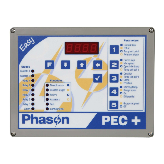
Becoming familiar with the PEC Plus The PEC Plus has a four-character LED display, status LEDs for each variable stage and relay, function LEDs, and 10 buttons for programming and interacting with the control. - Page 16 The four-character, seven-segment LED display shows ambient temperatures, alarm messages, and programming information. If you leave the PEC Plus in a menu or display other than the main display, the control returns to the main display after five minutes without any key presses. The only exceptions are stage test mode and temperature test mode;...
-
Page 17: Menu Layout
PEC Plus user manual Becoming familiar with the PEC Plus Menu layout The table below shows the layout of the PEC Plus menu system. Growth curve Configuration >>Parameter A<< Alarm enable (ALEn) 1 Current day High temperature (KieN) 2 Curve step... -
Page 18: Entering A Pin
Chapter 1: Introducing the PEC Plus Phason Entering a PIN If security is enabled, users must enter the PIN (personal identification number) before they can access the control’s functions. After entering a PIN, the control will not ask again until five minutes have passed since the last key press. -
Page 19: Chapter 2: Installing Your Pec Plus
2. Using on page 84, list all the equipment you want to control Appendix D: Installation worksheet using this PEC Plus. Install the equipment and make your electrical connections according to the sheet. 3. Using on page 86, decide which relays and variable... -
Page 20: Electrical Ratings
PEC Plus. Lightning does not have to actually strike a power line to transmit a surge. Surge suppression devices offer some protection from power surges. Because it is not possible to internally protect this product completely from the effects of power surges and other transients, Phason highly recommend that you install external surge suppression devices. -
Page 21: Precautions, Guidelines, And Warnings
Servicing and maintaining your PEC Plus The PEC Plus must be installed by a qualified electrician. Before installing or servicing the PEC Plus, switch OFF the power at the source. Install the PEC Plus and all equipment connected to it according to local electrical codes. - Page 22 Chapter 2: Installing your PEC Plus Phason Routing data wires Routing data wires in the same conduit as, or beside AC power cables, can cause electrical interference, erratic readings, and/or improper control. Data wires include of the following: Temperature probe and humidity sensor cables...
-
Page 23: Pec Plus Layout
What you need to know before installing your PEC Plus PEC Plus layout Voltage selection switch – set this switch to the correct voltage before installing your PEC Plus. Variable stage fuses (F1, F2) – 15 A, 250 VAC ABC-type ceramic; F1 variable stage 1, F2 for stage Variable stage terminals (VAR1, VAR2) –... -
Page 24: Mounting Your Pec Plus
Phason Mounting your PEC Plus 1. Select a location for your PEC Plus. Make sure you have enough cable and wire to reach all the equipment (fans, heaters, misters, curtains, etc.) that you want to control. 2. Remove the screws from the front cover and then gently lift it off. - Page 25 Feedback potentiometers Each actuator you connect must have a feedback potentiometer. The feedback potentiometer, which you connect to one of your PEC Plus’ two corresponding feedback terminals, lets the control know how far the actuator’s arm is extended. Most linear actuators are available with potentiometer feedback and internal adjustable limit switches.
- Page 26 Chapter 2: Installing your PEC Plus Phason To connect actuators Connect actuators to your PEC Plus as shown below. Refer to your actuator’s installation guide for information about its power supply requirements. AC-powered actuators DC-powered actuators If you are unsure of the potentiometer wiring for your actuator, read Determining on page 82.
-
Page 27: Connecting Single-Stage Heating Or Cooling Elements
Heating or cooling elements include equipment such as electric heaters, furnaces, single-speed fans, and curtains. The ratings of the equipment must not exceed the ratings of your PEC Plus’ relays. PEC Plus relay ratings: 10 A at 120/230 VAC, general-purpose (resistive) -
Page 28: Connecting Curtain Machines
Curtains are opened and closed to let in more air or less air, the idea being more air cools the building. You can connect up to three curtain machines to your PEC Plus. Each curtain machine you connect requires two relays: one for opening the curtain, and one for closing the curtain. The relays must be side-by-side pairs. -
Page 29: Connecting Variable-Stage Cooling Elements
Only permanent split capacitor motors appropriate for variable speed control, or shaded pole motors, can be used on the variable stages. If you are using three-phase power, connect the PEC Plus and the variable cooling equipment to the same phase. For more information, read Using three-phase power on page 20. -
Page 30: Using Three-Phase Power
Phason Using three-phase power If you are connecting your PEC Plus to a three-phase system, make sure to connect the control power and the variable cooling equipment to the same phase. Your PEC Plus must be powered from the same phases that supply the equipment. If your PEC Plus power and the variable stages are wired to different phases, the equipment will operate erratically. -
Page 31: Connecting An Alarm System
Connecting equipment to your PEC Plus Connecting an alarm system You can connect an alarm system to your PEC Plus’ alarm terminal. An alarm system can be a siren, alarm panel, or auto-dialer. Read your system’s installation guide for installation instructions and information about the type of system: normally open or normally closed. -
Page 32: Connecting Temperature Probes
Phason Connecting temperature probes The PEC Plus has four temperature probe terminals, TEMP1 to TEMP4. You can connect any of Phason’s standard 3K temperature probes to any of the probe terminals. All enabled probes are averaged to provide a more balanced temperature reading in the room. Probe 4 (TEMP4) can be used to monitor outdoor temperatures. -
Page 33: Extending Probe Cables
You can extend temperature probe cables to lengths of up to 500 feet. Follow the guidelines below and on page 22 when extending cables. Use two-wire 18 AWG jacketed cable. Phason recommends Belden # 9408, Alpha # 5052, or an equivalent. Extension cable is also available from Phason. For more information, contact your dealer or Phason. -
Page 34: Connecting The Power Source
Chapter 2: Installing your PEC Plus Phason Connecting the power source You can connect your PEC Plus to 120 or 230 VAC, 50 or 60 Hz power. Before connecting the power, set the voltage selection switch to the correct voltage. -
Page 35: Finishing The Installation
It is very important that the connections and the worksheets are the same, because the next step after closing the cover is to tell your PEC Plus which equipment is connected to each terminal. It is important so you can be sure you are controlling the equipment you think you are controlling. - Page 36 Chapter 2: Installing your PEC Plus Phason 2009-06-15...
-
Page 37: Chapter 3: Configuring Your Pec Plus
What you need to know before configuring your PEC Plus Configuring your PEC Plus means telling it what equipment it will be controlling and how it will be controlling that equipment. For example, your PEC Plus has 6 relay stages. You need to tell the stages if they will be controlling curtains, heating or cooling elements, or actuators. - Page 38 77 and then follow the instructions for correcting the Troubleshooting problem. Your PEC Plus’ built-in diagnostic tests are useful for testing your equipment after installing and configuring it. For more information, read Testing settings and on page 63.
-
Page 39: Configuring The Main Control Functions
Hysteresis – the number of degrees above or below the set point that equipment switches on or Setting the clock The PEC Plus has a clock that keeps track of the time for the daily high and low temperatures and the growth curves. -
Page 40: Selecting The Temperature Units
Chapter 3: Configuring your PEC Plus Phason The PEC Plus starts counting time as soon as it is connected to an incoming power supply. CONFIGURATION To set the clock 1. Press until the LED for CONFIGURATION is lit. Function (loc 2. -
Page 41: Configuring Temperature Probes
Configuring the main control functions Configuring temperature probes The PEC Plus has four temperature probe terminals, TEMP1 to TEMP4. You can connect any of Phason’s standard 3K temperature probes to any of the probe terminals. By default, probe 1 (TEMP1) is enabled and probes 2, 3, and 4 are not enabled. When enabled, probes 2, 3, and 4 can be averaged to provide a more balanced temperature reading in the room. -
Page 42: Configuring Hysteresis
Chapter 3: Configuring your PEC Plus Phason To configure temperature probes CONFIGURATION 1. Press until the LED for CONFIGURATION is lit. Function 2. Press until prob is displayed and then press Down Select prob 3. Press to select the probe you want to configure and... -
Page 43: Configuring Variable Stages
PEC Plus user manual Configuring variable stages Configuring variable stages Your PEC Plus’ two variable stages ( ) control elements that operate with gradually VAR1 VAR2 increasing voltage, such as variable speed fans. Variable-speed fan example Increase voltage Configuring variable stages means selecting whether each stage is enabled as a cooling element, for example a fan, or is off. -
Page 44: Configuring Relays
Configuring relays for actuators You can connect up to two actuators to a PEC Plus. Each actuator you connect requires two relays: one for extending the actuator arm (opening the inlet), and one for retracting the arm (closing the inlet). -
Page 45: Calibrating Actuators
PEC Plus know the position of the actuator when it is fully extended and fully retracted. The PEC Plus uses the limits to define the range of motion it uses to position the inlets. These limits tell the control how much to adjust when you want the actuators, for example, only 25% extended. -
Page 46: Configuring Relays For Curtains
To calibrate actuators 1. Loosen the four screws in the PEC Plus enclosure and then gently remove the cover. Make sure not to disconnect the ribbon cable. 2. Remove and then replace the ACTUATOR PRESENT jumper on the pins for the actuator (ACT1 for actuator 1 and ACT2 for actuator 2). -
Page 47: Configuring Relays For Single-Stage Heating And Cooling Or Duty Cycles
PEC Plus user manual Configuring relays To configure relays for curtain control CONFIGURATION 1. Press until the LED for CONFIGURATION is lit. Function 2. Press until rly is displayed and then press Down Select The display shows rly1. 3. Press... - Page 48 Chapter 3: Configuring your PEC Plus Phason CONFIGURATION To configure relays for single-stage heating or cooling (no duty cycle) 1. Press until the LED for CONFIGURATION is lit. Function 2. Press until rly is displayed and then press Down Select The display shows rly1.
-
Page 49: Testing The Configuration
You can test the configuration using the PEC Plus’ test mode. Test mode allows you to operate the equipment, regardless of temperature or time. As you operate each piece of equipment, visually check to see if that equipment is doing what you tell it. - Page 50 Chapter 3: Configuring your PEC Plus Phason 2009-06-15...
-
Page 51: Chapter 4: Programming The Pec Plus
Chapter 4: Programming the PEC Plus Chapter 4 discusses how to program your PEC Plus with the settings it uses to control your equipment. Topics in chapter 4 include: below What you need to know before programming your PEC Plus... -
Page 52: Programming Target Temperatures
Growth curve Group set point The PEC Plus uses one or the other. If the growth curve is enabled, the control uses the growth curve settings. If the growth curve is not enabled, the control uses the group set point. -
Page 53: Programming The Growth Curve
As they grow older, they need a steadily lower temperature. Using the growth curve, you can have your PEC Plus automatically adjust the temperatures. For example, start at 76°F for 1 day, drop to 74°F for 1 day, then to 71°F for 21 days, 68°F for 14 days, and so on. - Page 54 (86.5°F) and the starting set point for the next 85.0 step (85°F) is 1.5°F. 83.5 81.0 The PEC Plus divides the temperature difference 78.0 by the duration 1.5 ÷ 10=0.15 and then 74.0 automatically adjusts the set point by 0.15°F each day for 10 days.
- Page 55 PEC Plus user manual Programming target temperatures Parameter Description Options/range Displayed as 1 – Current day The current day of the growth curve 0 to 365 coff to c365 2 – Step The step of the growth curve you are...
-
Page 56: Programming The Stages
Chapter 4: Programming the PEC Plus Phason 6. To view the start temperature, press The display shows the current setting. 7. To change the start temperature, press and then press Down Select The control returns to the Parameter menu. 8. Repeat steps 2 to 7 for each step you want to program. - Page 57 PEC Plus user manual Programming the stages How variable stage cooling works When the temperature is below the “off at” temperature, the fan is off. When the temperature reaches the “off at” temperature, the fan runs at the idle speed. The fan continues to run at the idle speed until the temperature rises to the “set point”...
- Page 58 Chapter 4: Programming the PEC Plus Phason Use the on page 90 when programming variable Variable stage settings worksheet stages. To program variable stages VARIABLE STAGES 1. Press until the LED for VARIABLE STAGES is lit. Function The display shows uar1 (variable stage 1).
-
Page 59: Programming Actuators
PEC Plus user manual Programming the stages Programming actuators Before programming the actuator relays, make sure you have properly configured the relays and calibrated the actuators. For more information, read on page 34 Configuring relays for actuators on page 35. - Page 60 You can use actuator control for curtain machines only if they have feedback potentiometers. Do not use actuator control for curtain machines without potentiometers. This can burn out the curtain machines. For information about programming the PEC Plus to control curtain machines without potentiometers, read Programming curtain control on page 52.
- Page 61 PEC Plus user manual Programming the stages To program actuator stages ACTUATORS 1. Press until the LED for ACTUATORS is lit. Function a(t1 The display shows a(t1 (Actuator 1). 2. Press to toggle between programming actuator 1 and Down actuator 2 and then press Select The display shows pard (parameter D).
-
Page 62: Programming Curtain Control Relays
Chapter 4: Programming the PEC Plus Phason Programming curtain control relays Curtains control the temperature by adjusting the air flow into the facility. Each curtain has six settings. Set point – the temperature at which the curtain holds its position. - Page 63 PEC Plus user manual Programming the stages Time (duration) Open off (02:00 mm:ss) After the curtain opens for the “open on” duration, it holds its position for the “open off” duration. Open on (00:30 mm:ss) If the temperature rises above the idle band, the curtain opens for this duration.
-
Page 64: Programming Heating And Cooling Elements And Duty Cycles
Chapter 4: Programming the PEC Plus Phason To program curtain relays RELAYS 1. Press until the LED for RELAYS is lit. Function The display shows rly1 (Relay 1). rly1 2. Press to scroll to the “open” relay and then press... - Page 65 PEC Plus user manual Programming the stages How normal duty cycles work For heating elements When the temperature is above the set point, the heating element is off. When the temperature drops below the set point, the element switches on for the on duration and then off for the off duration.
- Page 66 Chapter 4: Programming the PEC Plus Phason If you press a parameter button that has no function for the relay, the display shows ----. Press to return to the previous display. Back Use the on page 94 when setting up Heating and cooling elements worksheet heating and cooling elements or based duty cycles.
- Page 67 PEC Plus user manual Programming the stages To program normal duty cycles RELAYS 1. Press until the LED for RELAYS is lit. Function The display shows rly1 (Relay 1). rly1 2. Press to change between programming relays 1 to 6...
-
Page 68: Programming Alarm Settings
Actuator 1 jam Actuator 2 jam The alarm settings for your PEC Plus determine which alarm conditions are enabled, which are disabled, and their settings. All these work together to determine how and when the alarm relay activates (in other words, signals an alarm condition). - Page 69 PEC Plus user manual Programming the stages How alarm settings work Let’s say the High Temp alarm setting is 85.0°F. If the temperature rises to 86 degrees, but drops below 85 degrees 30 seconds later (before the minimum duration of 1 minute), the alarm relay does not activate.
- Page 70 Chapter 4: Programming the PEC Plus Phason To program high and low temperature alarm settings RELAYS 1. Press until the LED for RELAYS is lit. Function The display shows rly1 (Relay 1). ALARM 2. Press until the display shows LoaL (low temperature alarm)
-
Page 71: Chapter 5: Monitoring And Maintaining Your Pec Plus
Chapter 5: Monitoring and maintaining your PEC Plus Chapter 5 explains how to monitor the PEC Plus after you have installed, configured, and programmed it. Topics in chapter 5 include: below Monitoring your PEC Plus on page 63 Testing settings and equipment... -
Page 72: Displaying High And Low Temperatures
The exceptions to the one minute minimum are the actuator 1 jam and actuator 2 jam alarms. Actuator jam alarms activate immediately after the PEC Plus detects an actuator jam. When an alarm occurs, the alarm relay activates, the LED for ALARM switches on, and the alarm message displays. -
Page 73: Testing Settings And Equipment
Press Select If there was only one alarm message, the PEC Plus clears the message and returns to the main display. If there are additional alarm messages, the PEC Plus displays the next message. For a list of alarm messages, their descriptions, and possible resolutions, read on page 77. -
Page 74: Using Temperature Test Mode
When the PEC Plus is in stage test mode, it does not operate the equipment according to the measured temperature. The PEC Plus does not exit test mode on its own. When you are finished testing, press until the control exits test mode. -
Page 75: Using The Actuator 1 And 2 Test Utilities
The variable stages and relays remain operating according to the test temperature until you exit temperature test mode. When the PEC Plus is in temperature test mode, it does not operate the equipment according to the measured temperature. -
Page 76: Using Pin Security
Using PIN security The PEC Plus has a PIN security feature you can use to control who makes changes to your system and its settings. When you enable security, users must enter the PIN (personal identification number) before they can access the control’s functions. -
Page 77: Servicing And Maintaining Your Pec Plus
The PIN resets to 1111. Servicing and maintaining your PEC Plus Servicing and maintaining your PEC Plus will extend the life of the control and your equipment. Before installing or servicing your PEC Plus, switch OFF the power at the source. - Page 78 Chapter 5: Monitoring and maintaining your PEC Plus Phason Moisture Moisture will not cause problems with the control if you take proper care during installation. 1. After the first two weeks of operation, remove the cover from the unit and check inside for moisture.
-
Page 79: Restoring The Factory Defaults
Servicing and maintaining your PEC Plus Restoring the factory defaults When your PEC Plus leaves the factory, it comes with default settings and configuration. When you program your PEC Plus, you change its configuration and settings. Resetting your PEC Plus erases all the configuration and settings you programmed and restores them to what they were when the control left the factory. - Page 80 Chapter 5: Monitoring and maintaining your PEC Plus Phason To save your settings 1. Loosen the four screws in the PEC Plus enclosure and then gently CONFIGURATION remove the cover. Make sure not to disconnect the ribbon cable. 2. Insert the PEC+ Saver into the connector marked SAVER on the Saue inside top-left of the cover.
-
Page 81: Displaying The Firmware Version
XP) have version numbers, the firmware has a version number. If you need to contact Phason Customer Support about your PEC Plus, you might need to provide them with the firmware version of your control. For more information about technical support, read at the front of the manual. - Page 82 8. Replace the cover and then tighten the four screws. To update the firmware using the “power off” method 1. Loosen the four screws in the PEC Plus enclosure and then gently remove the cover. Make sure not to disconnect the ribbon cable.
-
Page 83: Appendixes
I want the actuator to be at this position (stage position) percent.” For more information, read on page 49. Programming actuators control Control elements are devices connected to your PEC Plus, such as fans, heaters, elements actuators, and so on. 31040003... - Page 84 Programming heating and cooling elements firmware The internal program instructions of your PEC Plus. You can update the firmware version of your PEC Plus to the latest version using a PEC+ Updater. For more information, read on page 71. Updating the firmware...
- Page 85 Minimum duration is the minimum amount of time and alarm condition must be duration present before the PEC Plus signals an alarm. The minimum duration, one minute, prevents alarms from activating when the temperature rises or drops for just a few seconds.
- Page 86 Understanding power surges and surge on page 9. suppression terminal block The part of your PEC Plus where you connect the wires for incoming power, control elements, and so on. For more information, read on page 13. PEC Plus layout voltage Electromotive force or potential difference, usually expressed in volts.
-
Page 87: Appendix B: Troubleshooting
If you are having a problem using your PEC Plus, see if the problem is described in the table on page 79 and then follow the directions for correcting the problem. - Page 88 Appendixes Phason A temperature probe is damaged Replace or reconnect the pbad or disconnected. temperature probe. The control should recover automatically. Probe damage alarm If another probe is available, the control uses it. If probe averaging is on, the defective probe is excluded from the average.
-
Page 89: Troubleshooting
The following table lists some problems, possible causes, and possible solutions. If you are having a problem using your PEC Plus, see if the problem is described in the Troubleshooting table and then follow the directions for correcting the problem. - Page 90 Appendixes Phason Variable fan runs at Incorrect wiring Correct the wiring. For more maximum information, read Connecting variable-stage cooling elements on page 19. The minimum idle speed is too Decrease the minimum idle speed high. setting. For more information, read Programming variable stages on page 46.
- Page 91 PEC Plus user manual Appendix B: Troubleshooting Relay does not switch load Incorrect wiring Correct the wiring. For more information, read the appropriate installation section. The relay is configured as OFF. Configure the relay properly. For more information, read Configuring relays starting on page 34.
-
Page 92: Determining Correct Actuator Feedback Wiring
Appendixes Phason Determining correct actuator feedback wiring After installing a new actuator or potentiometer, or due to age-related potentiometer wear, the actuator might not move correctly. Common symptoms include: The actuator oscillating back and forth The actuator not traveling the full stroke during calibration The feedback potentiometer wiring must be properly connected to the control. -
Page 93: Appendix C: Factory Defaults
Appendix C: Factory defaults Appendix C: Factory defaults When your PEC Plus leaves the factory, it comes with default settings and configuration. When you configure and set up your PEC Plus, you change its settings. Resetting your PEC Plus erases all the configuration and settings you programmed and then restores the settings to what they were when the control left the factory. -
Page 94: Appendix D: Installation Worksheet
Use the worksheet on the next page to list all the equipment (fans, heaters, curtains, and so on that you want your PEC Plus to control. We recommend you make a copy of the worksheet before filling it in incase you need more than one sheet or you make a mistake. - Page 95 PEC Plus user manual Appendix D: Installation worksheet Stage/relay Equipment to connect Example: VAR1 36-inch variable speed fan, 2.5 FLA, 3/4 HP VAR1 VAR2 RELAY1 RELAY2 RELAY3 RELAY4 RELAY5 RELAY6 ALARM 31040003...
-
Page 96: Appendix E: Configuration Worksheets
Appendixes Phason Appendix E: Configuration worksheets Use the on page 84 when completing the configuration Installation Worksheet worksheets. Main control function worksheet For each item, circle or write in the configuration. Item Description Configuration °C °F Units The unit of measure for temperature. -
Page 97: Variable Stage Configuration Worksheet
PEC Plus user manual Appendix E: Configuration worksheets Variable stage configuration worksheet For each variable stage: Enter a description (for reference only) Put a check mark in the appropriate column for how to configure the relay. Example Stage Description Stage 1 fan... -
Page 98: Relay Configuration Worksheet
Appendixes Phason Relay configuration worksheet For each relay: Enter a description (for reference only) Put a check mark in the appropriate column for how to configure the relay. Relay configuration example Relay Description Inlet open Inlet close 36-inch fan Electric heat... -
Page 99: Appendix F: Settings Worksheets
You can have up to seven steps in a growth curve. Each step has a starting temperature set point and a duration. The PEC Plus automatically calculates the set points for the days between the steps and adjusts the set points at midnight each day. Individual set points for the variable and fixed stages are adjusted relative to the growth curve temperature for that particular day. -
Page 100: Variable Stage Settings Worksheet
Appendixes Phason Variable stage settings worksheet Setting Variable 1 Variable 2 Range/On full at Set point Off at Idle speed Temperature in °F/°C, range: 0.0 to 37.7°C (32.0 to 99.9°F) Idle speed in %; range: 0 to 100 % If you need to connect more cooling elements than you have relays available, and you are not using both variable stages, you can use an available variable stage as an ON/OFF stage (for 120/230 VAC-powered equipment only). -
Page 101: Actuator Settings Worksheet
PEC Plus user manual Appendix F: Settings worksheets Actuator settings worksheet Each actuator has six stages. The settings for the stages include the set point temperature, position, and differential temperature. Actuator position 100% Stage 5 differential Stage 5 set point... - Page 102 Appendixes Phason Setting Actuator 1 Actuator 2 Description Minimum (stage 0) The temperature below which the actuator is Set point closed The percentage the actuator is open when the Position temperature is at or above the minimum set point Stage 1...
-
Page 103: Curtain Worksheet
PEC Plus user manual Appendix F: Settings worksheets Curtain worksheet Curtains control the temperature by adjusting the air flow into the facility. Each curtain has six settings. Set point – the temperature at which the curtain holds its position. Idle band – the buffer around the set point within which the curtains hold their position. -
Page 104: Heating And Cooling Elements Worksheet
Appendixes Phason Heating and cooling elements worksheet Heating and cooling elements control the temperature by switching single-stage heating equipment such as electric heaters, or cooling equipment such as misters ON or OFF. There are three types of heating and cooling element setups: standard, duty cycle, and advanced duty cycle. -
Page 105: Alarm Settings Worksheet
Appendix F: Settings worksheets Alarm settings worksheet The alarm settings for your PEC Plus determine which alarm conditions are enabled, which are disabled, and their settings. All these work together to determine how and when the alarm relay activates (in other words, signals an alarm condition). -
Page 106: Index
PEC Plus user manual Index Index group set point........42–43 AC actuators ......... See actuators growth curve ......... 43–46 hysteresis ........... 32 access code ........See PINs relays............34 acknowledging alarms ......62–63 single-stage cooling/heating ..37–38, 54–57 Actuator Position Sensor ........ 15 temperature probes ...... - Page 107 33, 46–48 low temperature display ......61–62 programming checklist ........41 main display ............. 6 real-time clock ..........29 maintaining the PEC Plus ......67–68 relays ..See also single-stage cooling/heating menu..............7 ratings ............10 moisture............68 terminal locations........
- Page 108 ..........2, See PINs temperature test mode......64–65 selecting temperature units ......30 testing..........39, 63–66 servicing the PEC Plus ......67–68 three-phase power ......... 20 settings ........See programming time........See date and time settings saver......See PEC+ Saver...
- Page 112 Phason Inc. 2 Terracon Place Phone: 204-233-1400 E-mail: support@phason.ca Winnipeg, Manitoba, Canada Fax: 204-233-3252 Web site: www.phason.ca R2J 4G7...
Need help?
Do you have a question about the PEC Plus and is the answer not in the manual?
Questions and answers