
Subscribe to Our Youtube Channel
Related Manuals for T-Drill PLUS 115 SS:

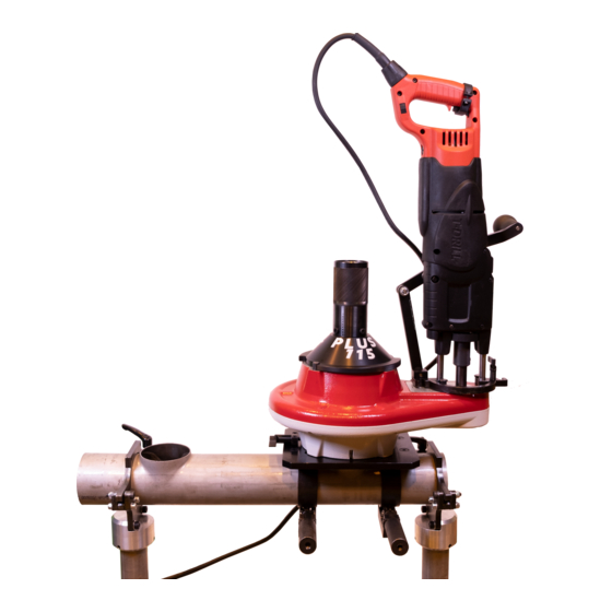
Summary of Contents for T-Drill PLUS 115 SS:
- Page 1 INSTRUCTION MANUAL SPARE PARTS LIST PORTABLE COLLARING SYSTEM PLUS 115 SS S-80 FOR STAINLESS STEEL BRANCHING...
- Page 2 Your local dealer is: Copyright © 2021 T-DRILL Oy. All rights reserved. This manual, or parts thereof, may not be reproduced in any form or by any means, nor translated into any other language without a written permission of T-DRILL Oy Is has been our aim to elaborate this instruction book with the greatest possible care and attention.
-
Page 3: Table Of Contents
2.1 General safety instructions for work area ..............7 2.2 Safety instructions for tool ..................7 2.3 Safety instructions for tee forming ................8 3. T-DRILL PLUS 115, general ....................9 3.1 Technical data ......................9 4. Transport, Handling and Storage .................. 10 5. - Page 4 15.17 Collaring head 3” – 4” 5700150 D SSt ..............66 15.18 Clamps (2290159) ....................68 15.19 T-Drill T-65 collaring machine EU 5330722 ............69 15.20 T-Drill T-65 collaring machine US 5330717 ............69 15.21 The T-65 Tee Forming Unit .................. 71...
-
Page 5: Notes On The Use Of The Instruction Manual
1.1 GENERAL This instruction book contains the instructions for use, maintenance and setting of the T-DRILL PLUS 115 capacity expanding attachment for the heavy duty T-65 SS Collaring Machine. Before proceeding with the operation of the machine, read the safety instructions in chapter 2 “General safety instructions. -
Page 6: General Safety Instructions
The T-DRILL T-65 is designed for use with MILWAUKEE power unit. Using ¨ any other power units with the T-DRILL T-65 tee forming unit is not allowed. IMPORTANT! Warranty is void if the power unit is detached from the tee forming unit! -
Page 7: General Safety Instructions For Work Area
PLUS 115 PORTABLE COLLARING SYSTEM 2.1 GENERAL SAFETY INSTRUCTIONS FOR WORK AREA Keep work area clean – Cluttered areas and benches invite injuries. Consider work area environment – Don’t use power tool in humid or wet conditions. Keep work area well illuminated. Don’t use power tool in the presence of flammable liquids or gases. -
Page 8: Safety Instructions For Tee Forming
INSTRUCTION MANUAL Have your tool repaired only by T-DRILL – This electric tool is in accordance with the relevant safety requirements. Repairs should be carried out only by certified persons using original spare parts; otherwise, this may result in considerable danger to the user. -
Page 9: T-Drill Plus 115, General
The PLUS 115 must be used with the T-DRILL T-65 grounded power tool with it’s own connecting cord and a foot pedal for controlling of the T-65. This is because, when milling, the other hand drives the ellipse and the other is needed for lubricating the milling pin. -
Page 10: Transport, Handling And Storage
PLUS 115 transport boxes and top shelf Storage Storing of T-Drill machines and tools: Clean machines, tools and parts from lubricant, chips and other debris, lubricate all components lightly with protective oil to prevent rust. Use, for example, Zerust, WD40 or other light rust protection oil. Keep the machine and... -
Page 11: Introduction
PORTABLE COLLARING SYSTEM 5. INTRODUCTION 5.1 THE PARTS OF THE T-65 Main parts: 1. T-DRILL tee forming unit, 2. Power unit, 3. Connecting cord, 4. T-DRILL head, 5. Tube support. The speed selector The feed mechanism lever 1. The speed selector knob is on the top of the gearbox of the outlet forming unit. To engage high or slow speed, turn the selector knob 180°. -
Page 12: Parts Of The Plus 115
INSTRUCTION MANUAL 5.2 PARTS OF THE PLUS 115 1. Lead screw, 2. Collaring head (not visible), 3. PLUS 115 unit, 4. Base plate, 5. Ring clamps, 6. T-65 machine, 7. Drilling unit, 8. Lubricant, 9. Elliptic pilot hole device, 10. Facing tool, 11. -
Page 13: The Elliptic Pilot Hole Device
PLUS 115 PORTABLE COLLARING SYSTEM 5.2.1 THE ELLIPTIC PILOT HOLE DEVICE Main parts of the elliptic pilot hole device T-65 locking lever Ellipse pilot hole operation nut Milling pin Scale locking screw for A-scale Milling pin locking screws (3 pcs) Scale adjustment for A-scale Milling spindle 10 Scale adjustment and locking screw for... -
Page 14: Information About Accessories
T-DRILL recommends the use of T-DRILL lubricant that should be applied generously; 1. Every time before drilling through, and constantly during the milling of the pilot hole to the milling pin. -
Page 15: Taking The Machine Into Operation
PLUS 115 PORTABLE COLLARING SYSTEM 7. TAKING THE MACHINE INTO OPERATION Creating a collar with your PLUS 115 and completing the joint is simple. Because it is a new process we recommend you to read the following instructions carefully and then practice a few times on some pieces of scrap tubing. -
Page 16: The T-Drill Milling Spindle
To remove the T-DRILL milling pin spindle (2) from the chuck (1), rotate the locking ring as far it will go. Turn the T-DRILL milling pin spindle to the same direction one quarter of a turn (1/4) at the same time pulling it straight out. Release the lock ring. -
Page 17: Foot Pedal
PLUS 115 PORTABLE COLLARING SYSTEM Chucking the T-DRILL milling pin spindle (and removing it): 1. Locking ring, 2. Milling pin spindle. 7.3 FOOT PEDAL The foot pedal is used to control the T-65 power unit, as when milling, the other hand drives the ellipse device, and the other is required for lubricating of the milling pin. -
Page 18: Detachment And Attachment Of The T-65 Connecting Cord
INSTRUCTION MANUAL 7.3.1 DETACHMENT AND ATTACHMENT OF THE T-65 CONNECTING CORD When delivered the T-65 power unit is fitted with a quick disconnect connecting cord, which allows quick replacement of the cord in field conditions. The European type of connecting cord. The American type of connecting cord. -
Page 19: Plus 115 Collaring Process
PLUS 115 PORTABLE COLLARING SYSTEM 8. PLUS 115 COLLARING PROCESS 8.1 CLAMPS AND BASE PLATE 1. Choose the ring clamps according to the run tube diameter and fix the clamps to the base plate. Attachment takes place with the clamp locking pins in the base plate. -
Page 20: Making Of The Pilot Hole With Elliptic Device
INSTRUCTION MANUAL The base plate and elliptic pilot hole device can be attached to the tube in only one position: The base plate locking lever pointing to the left, and the pilot hole device adjustment part in front of the operator. 8.2 MAKING OF THE PILOT HOLE WITH ELLIPTIC DEVICE Adjustment of the pilot hole measures A and B The A and B dimensions of the ellipse are... - Page 21 PLUS 115 PORTABLE COLLARING SYSTEM The milling spindle is fastened to the T-65. The spindle is pushed through the bearing in the pilot hole cutter (1). The machine is then rotated counterclockwise so that the screws in the pilot hole cutter go into the slots (2). At this point, the locking lever can be locked (3). Turn T-65 machine back and forth to see that the machine is properly locked.
-
Page 22: Interruption Of Pilot Hole Milling
INSTRUCTION MANUAL When the drill has passed through the pipe wall, switch the ratchet reversing lever and start turning by the ratchet counterclockwise. Do not use too much force, but try to keep the milling in motion without stopping. Remember to lubricate the milling pin. When the entire ellipse is milled, lift the T-65 by the handle and only after the machine is lifted fully, stop the drill. -
Page 23: Making Of The Collar
PLUS 115 PORTABLE COLLARING SYSTEM 8.3 MAKING OF THE COLLAR 8.3.1 COLLARING HEAD ADJUSTMENT 1. Choose the collaring head according to the branch tube. Collaring head 1 (forming pin diameter 15 mm) for O.D. dimensions 54 - 87 mm / 2” - 2½” and collaring head 2 (forming pin diameter 18 mm) for O.D. -
Page 24: Collaring With Plus 115
INSTRUCTION MANUAL 8.3.2 COLLARING WITH PLUS 115 1. Place the PLUS 115 unit on top of the base plate assembly so that the locking pins underneath the unit match the four holes in the base plate assembly. Turn the unit counter-clockwise so that it locks. You may also place the PLUS 115 unit sideways to 90°... - Page 25 PLUS 115 PORTABLE COLLARING SYSTEM 4. Before engaging the lead screw, it must be rotated to the full length by hand. Engage the lead screw onto the collaring head so that the drive pin of the shank is in the groove of the lead screw.
- Page 26 INSTRUCTION MANUAL 6. Tum the speed selector knob on the T-65 to position I . You may have to “pump” the foot pedal to get it engaged. 7. Start the drill by pressing the foot pedal. The forming pins are extended automatically to the collaring position.
-
Page 27: Facing
PLUS 115 PORTABLE COLLARING SYSTEM 8.4 FACING 1. Adjust the wanted facing height. The adjustment is made by rotating the facing tool handwheel to the wanted scale reading. To do that you have to loosen the locking wheel under the handwheel. After the adjustment, tighten the locking wheel. 2. -
Page 28: Fine Adjustment Of The Collaring Tool
INSTRUCTION MANUAL 9. FINE ADJUSTMENT OF THE COLLARING TOOL To obtain appropriate joint clearance a fine adjustment is occasionally needed. 1. Extend forming pins to the collaring position. 2. Note the position of the hash mark on the cylindrical cover in relation to a mark on the cover plate. -
Page 29: Stalling
PLUS 115 PORTABLE COLLARING SYSTEM 10. STALLING If the PLUS 115 is overloaded, the adapter will break and the collaring head will stall. If this occurs, do the following: 1. Detach the power cord from the T-65 machine and remove the T-65 from the PLUS 115 unit. -
Page 30: Maintenance
INSTRUCTION MANUAL 11. MAINTENANCE All servicing should be done only by T-DRILL. The PLUS 115 unit is lubricated for life and doesn’t need any extra maintenance. Clean dust and dirt from machine surface weekly. 11.1 PILOT HOLE CUTTER FOR ELLIPTIC PILOT HOLE Milling pin size 11,3 TiAlN is suitable for all collar sizes, others can be used, if desired. -
Page 31: Plus 115 Capacity And Instruction Chart
PLUS 115 PORTABLE COLLARING SYSTEM 12. PLUS 115 CAPACITY AND INSTRUCTION CHART t = max. wall thickness of stainless steel pipe in mm BRANCH OUTLET RUN PIPE MAX. WALL THICKNESS O.D. 33.7 42.4 48.3 60.3 76.1 88.9 114.3 139.7 168.3 219.1 Nom. -
Page 32: Pilot Hole Table For Plus 115
INSTRUCTION MANUAL 12.1 PILOT HOLE TABLE FOR PLUS 115 Small tool: A = 36 and B 25, for collars 1.1/2” - 2.1/2” Large tool: A = 50 and B 33, for collars 3” - 4” Run pipe Run pipe NS Branch pipe Branch pipe Pilot hole... - Page 33 PLUS 115 PORTABLE COLLARING SYSTEM Run pipe Run pipe NS Branch pipe Branch pipe Pilot hole Pilot hole Max wall O.D. mm inch O.D. mm NS inch a mm b mm thickness s 60,3 76,1 2¾ 88,9 114,3 273,0 48,3 1½...
-
Page 34: Pilot Holes For Stainless Steel Pipes, Wall Thickness ≤ 2.0Mm
INSTRUCTION MANUAL 12.2 PILOT HOLES FOR STAINLESS STEEL PIPES, WALL THICKNESS ≤ 2.0MM This table is indicative only. The values depend on the pipe materials and wall thicknesses as well as on the condition of the tool used. 1. Run tube, 2. Branch Run pipe O.D. - Page 35 PLUS 115 PORTABLE COLLARING SYSTEM Run pipe O.D. mm Branch pipe O.D. mm Pilot hole a mm Pilot hole b mm 82.5 104 / 108 63.5 82.5 63.5 82.5 159 / 164 63.5 82.5...
- Page 36 INSTRUCTION MANUAL Run pipe O.D. mm Branch pipe O.D. mm Pilot hole a mm Pilot hole b mm 193.7 63.5 82.5 219.1 63.5 82.5...
-
Page 37: T-Drill Standard Warranty
Product. In the event of a valid warranty claim, T-Drill shall, at its sole discretion, have the option of repairing or replacing the relevant part or parts free of charge and supplying them to the Customer. - Page 38 LIABILITY IN TORT OR OTHERWISE, EXCEPT IN THE CASE OF PERSONAL INJURY CAUSED DESPITE THE PROPER USE OF THE PRODUCTS, IF AND TO THE EXTENT REQUIRED BY APPLICABLE LAW. IN NO EVENT WILL THE AGGREGATE LIABILITY WHICH T-DRILL OR ITS OFFICERS, DIRECTORS, EMPLOYEES, AGENTS OR AFFILIATES MAY INCUR IN ANY ACTION OR PROCEEDING EXCEED THE TOTAL AMOUNT ACTUALLY PAID TO T-DRILL BY THE CUSTOMER FOR THE SPECIFIC PRODUCT THAT DIRECTLY CAUSED THE DAMAGE.
-
Page 39: Ordering Spare Parts
To proceeding this way you will prevent misunderstandings and you make sure to receive the correct spare parts and a prompt service. Contact information: Global USA, Mexico, Canada Spare part inquiries and orders sales@t-drill.fi sales@t-drill.com Technical support service@t-drill.fi service@t-drill.com Fax:... -
Page 40: Spare Parts List Plus 115 For Steel
SPARE PARTS LIST 15. SPARE PARTS LIST PLUS 115 FOR STEEL 15.1 PLUS 115 FOR STEEL (EU) 5700310 Part No. Name Size/Type Std./Manuf. 5700307 Gear 5700309 Leadscrew 5700291 Base plate 5700288 Pilot hole cutter 5700293 Drilling unit 5700301 Spindle 5700303 Transport box 5700304 Transport box... - Page 41 PLUS 115 PORTABLE COLLARING SYSTEM 15.1 PLUS 115 FOR STEEL (EU) 5700310...
-
Page 42: Plus 115 For Steel (Usa) 5700311
SPARE PARTS LIST 15.2 PLUS 115 FOR STEEL (USA) 5700311 Part No. Name Size/Type Std./Manuf. 5700307 Gear 5700309 Leadscrew 5700291 Base plate 5700288 Pilot hole cutter 5700293 Drilling unit 5700301 Spindle 6700300 Pointer 5700304 Transport box 5700303 Transport box 5290206 Locking Lever 5700317 Tool set... - Page 43 PLUS 115 PORTABLE COLLARING SYSTEM 15.2 PLUS 115 FOR STEEL (USA) 5700311...
-
Page 44: Gear 5700307
SPARE PARTS LIST 15.3 GEAR 5700307 Part No. Name Size/Type Std./Manuf. 1700042 Upper house 1700043 Lower housing 2700141 Middle bushing 4700052 Locking pin 4700054 Locking pin 4700053 Locking pin 4700047 Primary shaft 3700051 Adapter 4700055 Bushing 4700056 9021035 Groove ball bearing Ø140/Ø175x18 61828-HLU 9021054... - Page 45 PLUS 115 PORTABLE COLLARING SYSTEM 15.3 GEAR 5700307 Konekilpi liimataan Sikabond 500 Ruuvilukite...
-
Page 46: Lead Screw 5700309
Std./Manuf. 4700062 Leadscrew 3700063 Cover 4700064 Bushing 4700065 4700066 Limiter nut 9014079 Socket head cap screw M6x8 8.8 DIN 7984 9016004 Set screw M6x6 12.9 DIN 913 9028320 Male plug Ø28 Valkoinen muovi 6700305 Sticker Harmaa, T-DRILL PLUS 115 SS... - Page 47 PLUS 115 PORTABLE COLLARING SYSTEM 15.4 LEAD SCREW 5700309...
-
Page 48: Base Plate 5700291
SPARE PARTS LIST 15.5 BASE PLATE 5700291 Part No. Name Size/Type Std./Manuf. 6700290 Base plate 8003707 Index knob 22120_0376 9014020 Socket head cap screw M5x16 8.8 DIN 912 6700292 Clamp holder bar 9014316 Socket head cap screw M8x20 DIN 7991 4280104 Fastening pin 9028065... - Page 49 PLUS 115 PORTABLE COLLARING SYSTEM 15.5 BASE PLATE 5700291...
-
Page 50: Pilot Hole Cutter 5700288
SPARE PARTS LIST 15.6 PILOT HOLE CUTTER 5700288 Part No. Name Size/Type Std./Manuf. 6700268 Body 6700272 Base frame 6700275 Upper frame 8003708 Guide rail MGNR15R210CM 8003710 Guide rail MGNR12R140HM 8003709 Runner block MGN15CZFC 8003539 Runner block Hiwin MGN12CZFC 9114016 Socket head cap screw M3x12 8.8 DIN 912 8002259... - Page 51 PLUS 115 PORTABLE COLLARING SYSTEM 15.6 PILOT HOLE CUTTER 5700288 Part No. Name Size/Type Std./Manuf. 9016101 Set screw M4x5 12.9 DIN 914 9128016 Fixing lever M6x20 K1000.106.020.02 4700052 Locking pin 9013014 Self-locking nut DIN 985 9114070 Socket head cap screw M8x30 8.8 Zn DIN 912 9013035...
- Page 52 SPARE PARTS LIST 15.6 PILOT HOLE CUTTER 5700288 32 33...
-
Page 53: Pilot Hole Drill Bits
PLUS 115 PORTABLE COLLARING SYSTEM 15.6.1 PILOT HOLE DRILL BITS Part No. Name Size, standard, manufacturer 6310552 Drill 11,3 TiAlN For 21,3 head... -
Page 54: Trimming Device 5700118 A
SPARE PARTS LIST 15.7 TRIMMING DEVICE 5700118 A Part No. Name Size/Type Std./Manuf. 3700120 Body 3700121 Screw 3700122 Cover 4700123 Handwheel 4700124 Locking nut 4700125 4700126 Blade retainer 4700127 Locking pin 4290082 Bearing cap 4120156 Reversible Blade L=19 4120155 Blade fastener 4700145 Measuring scale (mm) - Page 55 PLUS 115 PORTABLE COLLARING SYSTEM 15.7 TRIMMING DEVICE 5700118 A...
-
Page 56: Drilling Unit 5700293 A
SPARE PARTS LIST 15.8 DRILLING UNIT 5700293 A Part No. Name Size/Type Std./Manuf. 6700270 Fastener 8003706 Index knob 22120.0314 6700282 Fixture 9014332 Socket head cap screw M5x20 DIN 7991 6330763 Hinge pin 6330894 Lever 6330765 Lever 8003595 Knob 6080257 M8/Ø10x50mm 8000988 Slide bearing Ø8 / Ø14 / Ø18-3... - Page 57 PLUS 115 PORTABLE COLLARING SYSTEM 15.8 DRILLING UNIT 5700293 A...
-
Page 58: Spindle 5700301
SPARE PARTS LIST 15.9 SPINDLE 5700301 Part No. Name Size/Type Std./Manuf. 6310530 Spindle shaft 6700248 Sliding shaft 9019007 Retaining ring Ø25x1.2 DIN 471 Bl1 9016004 Set screw M6x6 12.9 DIN 913... -
Page 59: Transport Box 5700303
PLUS 115 PORTABLE COLLARING SYSTEM 15.10 TRANSPORT BOX 5700303 Part No. Name Size/Type Std./Manuf. 5330774 Metal case 6700298 Moulded insert 6700302 Sticker Harmaa, T-DRILL PLUS 115 SS... -
Page 60: Transport Box 5700304
SPARE PARTS LIST 15.11 TRANSPORT BOX 5700304 Part No. Name Size/Type Std./Manuf. 5330774 Metal case 6700302 Sticker Harmaa, T-DRILL PLUS 115 SS 6700297 Moulded insert 6330895 Metal case 6700299 Moulded insert... -
Page 61: Locking Lever 5290206 A
PLUS 115 PORTABLE COLLARING SYSTEM 15.12 LOCKING LEVER 5290206 A Part No. Name Size/Type Std./Manuf. 3290200 Lock body 4290203 Pusher 4290201 Pivot pin 4290202 Handle 4290204 Shaft 9019002 Retaining ring Ø10x1 DIN 471 Bl1... -
Page 62: Tool Set 5700317
SPARE PARTS LIST 15.13 TOOL SET 5700317 Part No. Name Size/Type Std./Manuf. 8004534 Ratchet 8004535 Socket 19mm 9051010 Allen key SW = 14 DIN 911 9051014 Hexagon socket screw SW = 4 L=150 driver 9051017 Hexagon socket screw SW =3 Facom driver 84TZS.3... -
Page 63: Pedal Kit Eu 5700320
PLUS 115 PORTABLE COLLARING SYSTEM 15.14 PEDAL KIT EU 5700320 Part No. Name Size/Type Std./Manuf. 8004542 Foot switch F1-U2ZUN Bernstein 606.1700.004 9047245 Cable gland MS-M 20x1.5 EN 50262 Skintop 9048341 Power cord 3x1,5 mm2x3000 VSBA3x1,5 280 3M SSTL 2440221 15.15 PEDAL KIT US 5700321 Part No. -
Page 64: Collaring Head 2" - 2 ½" 5700148 C Sst
SPARE PARTS LIST 15.16 COLLARING HEAD 2” – 2 ½” 5700148 C SST Part No. Name Size/Type Std./Manuf. 2700069 Drill core 2"-2 1/2" 3290054 Adjuster cone 6291994 Forming pin Ø15 TiAlN 3700070 Drive drum 3700071 Bottom cover 3700072 Disk 4700073 Screw 4700074 Releasing screw... - Page 65 PLUS 115 PORTABLE COLLARING SYSTEM 15.16 COLLARING HEAD 2” – 2 ½” 5700148 C SST...
-
Page 66: Collaring Head 3" - 4" 5700150 D Sst
SPARE PARTS LIST 15.17 COLLARING HEAD 3” – 4” 5700150 D SST Part No. Name Size/Type Std./Manuf. 2700077 Drill core 3"-4" 3700117 Forming pin Ø18(128/135 long) TiAlN 3290054 Adjuster cone 3700070 Drive drum 3700071 Bottom cover 3700072 Disk 4700073 Screw 4700074 Releasing screw 4700090... - Page 67 PLUS 115 PORTABLE COLLARING SYSTEM 15.17 COLLARING HEAD 3” – 4” 5700150 D SST...
-
Page 68: Clamps (2290159)
SPARE PARTS LIST 15.18 CLAMPS (2290159) Part No. Name Size/Type 4290194 Ring Clamps NS 2 ½” 4290195 Ring Clamps NS 3” 4290196 Ring Clamps NS 4” 4290199 Ring Clamps NS 6” 4290240 Ring Clamps NS 8” 4290170 Ring Clamps Ø 73,0 4290173 Ring Clamps Ø... -
Page 69: T-Drill T-65 Collaring Machine Eu 5330722
PLUS 115 PORTABLE COLLARING SYSTEM 15.19 T-DRILL T-65 COLLARING MACHINE EU 5330722 15.20 T-DRILL T-65 COLLARING MACHINE US 5330717 Pos Part No. Description Size/type 5330158 Power Unit 120 V USA 5330160 Power Unit 230 V Europe 5330154 T-65 Tee Forming Unit... - Page 70 SPARE PARTS LIST 15.21 THE T-65 TEE FORMING UNIT 5330154 Pos Part No. Description Size/type Std./manuf. 5330156 Housing T-65 5330117 Lead Screw 5330097 Nut assembly 5540031 Gear 3330178 Gear changer 5330115 Shift Knob 4330099 Push rod 3330074 Lever 4540068 3330075 Fastening bush 4540056 3300056...
-
Page 71: The T-65 Tee Forming Unit
PLUS 115 PORTABLE COLLARING SYSTEM 15.21 THE T-65 TEE FORMING UNIT... -
Page 72: Ec Declaration Of Conformity
Name of the person authorized to compile the technical file: Juha Murtomäki, Ampujantie 32 FIN-66400 LAIHIA FINLAND Confirms that the manually operated accessory T-DRILL PLUS115 (type code 7005), together with the T-DRILL T-65 pipe collaring machine Complies with the regulations of the following other EU directives:... - Page 73 Safety Data Sheet according to Regulation (EC) No. 1907/2006 (REACH) according to Regulation (EU) 2015/830 Article No.: 317500 Isoform TD 50 Print date: 12.04.2021 Revision date: 07.04.2021 Version: 18.0 Issue date: 07.04.2021 Page 1 / 7 SECTION 1: Identification of the substance/mixture and of the company/undertaking 1.1.
- Page 74 Safety Data Sheet according to Regulation (EC) No. 1907/2006 (REACH) according to Regulation (EU) 2015/830 Article No.: 317500 Isoform TD 50 Print date: 12.04.2021 Revision date: 07.04.2021 Version: 18.0 Issue date: 07.04.2021 Page 2 / 7 287-477-0 01-2119519269-33 85535-85-9 alkanes, C14-17, chloro 60 <...
- Page 75 Safety Data Sheet according to Regulation (EC) No. 1907/2006 (REACH) according to Regulation (EU) 2015/830 Article No.: 317500 Isoform TD 50 Print date: 12.04.2021 Revision date: 07.04.2021 Version: 18.0 Issue date: 07.04.2021 Page 3 / 7 Advices on safe handling Avoid contact with skin, eyes and clothes.
- Page 76 Safety Data Sheet according to Regulation (EC) No. 1907/2006 (REACH) according to Regulation (EU) 2015/830 Article No.: 317500 Isoform TD 50 Print date: 12.04.2021 Revision date: 07.04.2021 Version: 18.0 Issue date: 07.04.2021 Page 4 / 7 Burning time: No data available Upper/lower flammability or explosive limits: Lower explosion limit: 0,6 Vol-%...
- Page 77 Safety Data Sheet according to Regulation (EC) No. 1907/2006 (REACH) according to Regulation (EU) 2015/830 Article No.: 317500 Isoform TD 50 Print date: 12.04.2021 Revision date: 07.04.2021 Version: 18.0 Issue date: 07.04.2021 Page 5 / 7 Based on available data, the classification criteria are not met. Practical experience/human evidence Overall Assessment on CMR properties The ingredients in this mixture do not meet the criteria for classification as CMR category 1A or 1B according to CLP.
- Page 78 Safety Data Sheet according to Regulation (EC) No. 1907/2006 (REACH) according to Regulation (EU) 2015/830 Article No.: 317500 Isoform TD 50 Print date: 12.04.2021 Revision date: 07.04.2021 Version: 18.0 Issue date: 07.04.2021 Page 6 / 7 Land transport (ADR/RID) ENVIRONMENTAL HAZARD Marine pollutant 14.6.
- Page 79 Safety Data Sheet according to Regulation (EC) No. 1907/2006 (REACH) according to Regulation (EU) 2015/830 Article No.: 317500 Isoform TD 50 Print date: 12.04.2021 Revision date: 07.04.2021 Version: 18.0 Issue date: 07.04.2021 Page 7 / 7 IATA-DGR International Air Transport Association – Dangerous Goods Regulations IBC Code International Code for the Construction and Equipment of Ships carrying Dangerous Chemicals in Bulk ICAO-TI...
- Page 80 More T-DRILL products for tube fabrication T-115 Transportable Collaring Unit for both S-54 AFT factory and on-site S-54 collaring unit with Automatic Feed Table -Collar sizes 21.3 - 114.3 mm (AFT). -Run tube sizes 33.7 - 323.9 mm SP-55/SP-110 Tube End Spinning machine for closing, reducing and expanding of copper tubes.
Need help?
Do you have a question about the PLUS 115 SS: and is the answer not in the manual?
Questions and answers