Advertisement
Quick Links
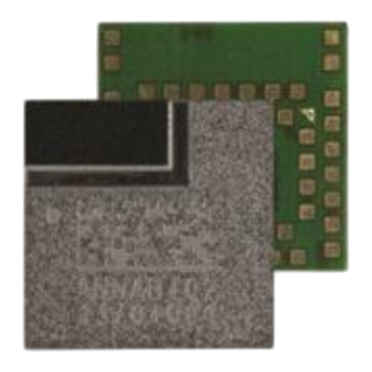
ANNA-B4 series
Stand-alone Bluetooth 5.1 low energy modules
System integration manual
Abstract
This manual provides a functional overview combined with best-practice design guidelines for
integrating ANNA-B4 stand-alone Bluetooth® 5.1 low energy modules in customer applications.
ANNA-B402 provides an open CPU architecture with a powerful MCU for customer applications,
while ANNA-B412 is delivered with pre-flashed u-connectXpress software. Targeted towards
hardware and software application engineers, the document describes the hardware design-in,
software, component handling, regulatory compliance, and testing of the module. It also includes list
of approved external antennas for use with the module.
UBX-21000517 - R03
C1-Public
0
3
www.u-blox.com
Advertisement

Related Manuals for Ublox ANNA-B4 Series


Summary of Contents for Ublox ANNA-B4 Series
- Page 1 ANNA-B4 series Stand-alone Bluetooth 5.1 low energy modules System integration manual Abstract This manual provides a functional overview combined with best-practice design guidelines for integrating ANNA-B4 stand-alone Bluetooth® 5.1 low energy modules in customer applications. ANNA-B402 provides an open CPU architecture with a powerful MCU for customer applications, while ANNA-B412 is delivered with pre-flashed u-connectXpress software.
- Page 2 ANNA-B4 series - System integration manual Document information Title ANNA-B4 series Subtitle Stand-alone Bluetooth 5.1 low energy modules Document type System integration manual Document number UBX-21000517 Revision and date 28-Jan-2022 Disclosure restriction C1-Public Document status explanation Draft For functional testing. Revised and supplementary data will be published later.
- Page 3 ANNA-B4 series - System integration manual Contents Document information ..........................2 Contents ................................3 Functional description ......................... 6 1.1 Overview ................................ 6 1.2 Example applications ..........................6 1.3 Product features ............................7 1.4 Block diagrams ............................8 1.5 Product description ............................ 9 ANNA-B4 ..............................
- Page 4 ANNA-B4 series - System integration manual 3.2 Antenna integration guidelines ......................22 3.3 Antenna connected through the RF pin ....................23 RF transmission line design ......................24 RF connector design ........................25 3.4 Supply interfaces ............................26 VCC application circuits ........................26 3.5 GND pins ..............................27 3.6 General layout guidelines ........................27...
- Page 5 ANNA-B4 series - System integration manual 7.2 European Union regulatory compliance ....................50 Radio Equipment Directive (RED) 2014/53/EU ................50 Compliance with the RoHS directive ....................50 7.3 FCC and IC compliance ..........................50 FCC compliance ..............................51 RF-exposure statement ........................52 End product user manual instructions..................52 End product labeling requirements ....................53...
- Page 6 Functional description 1.1 Overview The ANNA-B4 series are small, stand-alone Bluetooth 5.1 Low Energy (LE) wireless module that are particularly suited for harsh professional environments. Based on the Nordic Semiconductor nRF52833 chip that includes an integrated RF core and powerful Arm®...
- Page 7 ANNA-B4 series - System integration manual 1.3 Product features Figure 1: ANNA-B4 series main features summary UBX-21000517 - R03 Contents Page 7 of 74 C1-Public...
- Page 8 ANNA-B4 series - System integration manual 1.4 Block diagrams A block diagram of the ANNA-B4x2 module is shown in Figure ☞ Not all interfaces are supported by the u-connectXpress software in ANNA-B412 variants. For information about the interfaces supported specifically in ANNA-B412, see also the ANNA-B412 data sheet [6].
- Page 9 ANNA-B4 series - System integration manual 1.5 Product description ANNA-B4 Item ANNA-B402 / ANNA-B412 Bluetooth version Band support 2.4 GHz, 40 channels Typical conducted output power +8 dBm Max radiated output power with internal antenna (EIRP) +9 dBm Max radiated output power with external antenna (EIRP)
- Page 10 ANNA-B4 series - System integration manual Figure 3 shows the software architecture and implementation of software components for ANNA-B402 and ANNA-B412 modules. Figure 3: ANNA-B4 software structure Open CPU The open CPU architecture of ANNA-B402 series modules allows module integrators to build their own applications.
- Page 11 ANNA-B4 series - System integration manual u-connectXpress software ANNA-B412 modules are pre-flashed with u-connectXpress and bootloader software, which interfaces through an AT command interpreter to control customer application software running on host MCUs. Table 4 describes the feature support in the u-connectXpress software.
- Page 12 ANNA-B4 series - System integration manual System function interfaces 2.1 Main supply input The power for ANNA-B4 modules is provided through the VCC pins. ANNA-B4 uses an integrated DC/DC converter to transform the supply voltage presented at the VCC pin into a stable system core voltage.
- Page 13 2.3 Module reset ANNA-B4 series is reset by applying a low level on the RESET_N input pin, which is normally set high with an internal pull-up. A low logic level on this pin initiates an “external” or “hardware” reset of the module.
- Page 14 ANNA-B4 series - System integration manual ⚠ As the temperature sensor is embedded in the radio chip, any intensive processing can cause extra heat and impact the measurement accuracy. An external sensor is required if more accurate monitoring of the surrounding area is necessary.
- Page 15 ANNA-B4 series - System integration manual Figure 4 shows the low-power clock components used on the EVK-ANNA-B4 evaluation board. Figure 4: Connecting ANNA-B412 to an external crystal oscillator Component Value Note Crystal oscillator 32.768 kHz (20 ppm) EPSON FC-12M used on ANNA-B4 EVK...
- Page 16 CPU based application. See also the ANNA-B402 ANNA-B412 data sheets. Universal asynchronous serial interface (UART) ANNA-B4 series modules provide a Universal Asynchronous Serial Interface (UART) for data communication. The following UART signals are available: • Data lines (RXD as input, TXD as output) •...
- Page 17 The Inter-Integrated Circuit (I2C) interfaces can be used to transfer or receive data on a 2-wire bus network. The ANNA-B4 series contains up to two I2C bus interfaces and can operate as both master and slave using both standard (100 kbps) and fast (400 kbps) transmission speeds. The interface uses the SCL signal to clock instructions and data on the SDL signal.
- Page 18 ANNA-B4 series - System integration manual Function Description Default ANNA-B4 pin Configurable GPIOs ADC input 8/10/12-bit analog to digital converter Any analog Any analog Analog comparator Compare two voltages, capable of generating wake- input up events and interrupts PWM output...
- Page 19 Figure 6: Cortex debug connector pin out for SWD Thermal guidelines ANNA-B4 series modules have been successfully tested from –40 °C to +105 °C. ANNA-B4 modules are low-power devices that generate only a small amount of heat during operation. A good grounding should nonetheless be observed for temperature relief during high ambient temperatures.
- Page 20 ANNA-B4 series - System integration manual 2.11 ANNA-B1 to ANNA-B4 migration ANNA-B4 is pin compatible with ANNA-B1 and provides a simple migration path for upgrading applications with the extra features that ANNA-B4 modules deliver, including, increased memory, increased output power, coded physical layer (PHY), higher operating temperature range, and u-connectXpress secure-boot software.
- Page 21 ANNA-B4 series - System integration manual Consider the following when migrating from ANNA-B1 to ANNA-B4; that is, mounting an ANNA-B4 module onto a PCB originally designed for ANNA-B1: • The USB interface on open CPU, ANNA-B40 modules is not accessible as USBDP and USBDM signals on pins 34 and 35 are both connected to GND.
- Page 22 ANNA-B4 series - System integration manual Design-in 3.1 Overview All application circuits must be properly designed, but there are several points that require special attention during the application design. A list of these points, in order of importance, follows: •...
- Page 23 ANNA-B4 series - System integration manual • RF section may be affected by noise sources like hi-speed digital buses. Avoid placing the antenna close to high buses or consider taking specific countermeasures like metal shields or ferrite sheets to reduce the interference.
- Page 24 ANNA-B4 series - System integration manual RF transmission line design RF transmission lines, such as those that connect from the RF pin to the antenna or antenna connector, must be designed with a characteristic impedance of 50 . Figure 9...
- Page 25 ANNA-B4 series - System integration manual Contact the PCB manufacturer for specific tolerance of controlled impedance traces. As FR-4 material exhibits poor thickness stability it gives less control of impedance over the trace width. • For PCBs with components larger than 0402 and dielectric thickness below 200 µm, add a keep-out;...
- Page 26 ANNA-B4 series - System integration manual ☞ A de-facto standard for SMA connectors suggests that the use of reverse polarity connectors (RP-SMA) on Wi-Fi and Bluetooth end products can deter end users from replacing the antenna with higher gain types that exceed regulatory limits.
- Page 27 ANNA-B4 series - System integration manual The overall DC/DC efficiency of an SMPS depends on the current consumption during the active and idle states of the specific application. Although some DC/DC converters provide high efficiency with extremely light loads, their efficiency typically worsens when idle current drops below a few mA and reduces the battery life.
- Page 28 ANNA-B4 series - System integration manual • Verify the recommended maximum signal skew for differential pairs and length matching of buses. • Minimize the routing length. Ensure that the maximum allowable length for high-speed buses is not exceeded. Longer traces generally degrade signal performance.
- Page 29 ANNA-B4 series - System integration manual Table 14 describes the ESD immunity requirements as defined by CENELEC EN 61000-4-2, ETSI EN 301 489-1, ETSI EN 301 489-7, ETSI EN 301 489-24. Application Category Immunity level All exposed surfaces of the radio equipment and ancillary equipment Indirect Contact Discharge * ±8 kV...
- Page 30 ANNA-B4 series - System integration manual Open CPU software ANNA-B40 series modules are used in an open CPU configuration allows customer applications to be developed in a Nordic SDK environment in the ANNA-B4 module. 4.1 Zephyr Zephyr [20] is a widely adopted open-source Real Time Operating System (RTOS) that is supported on a multitude of chipsets, including the nRF52833 chip in the ANNA-B4 module.
- Page 31 ANNA-B4 series - System integration manual Getting started with the Nordic nRF5 SDK When working with the Nordic nRF5 SDK on the ANNA-B4 series module, follow the procedure below to get started with the Nordic Semiconductor toolchain and examples: Download and install the...
- Page 32 ANNA-B4 series - System integration manual An example of what a custom board support file could look like for the EVK-ANNA-B402 can be found in the u-blox short range GitHub repository [17]. The custom board can then be selected by adding a define of the symbol to your build.
- Page 33 ANNA-B4 series - System integration manual Modify the “ ” definition to define the BOARD_ BOARD_CUSTOM Figure 13: Pre-processor options for modifying the Define statement in SEGGER Embedded Studio Adding a board configuration to your project Another flexible way of adding a board to your project can be to add a new build configuration to your Segger Studio project and then use this to select the correct board file for your build.
- Page 34 ANNA-B4 series - System integration manual Configure the build configuration to use your board definition. Remember to undefine the configuration for the original board, assuming you are basing your project on an example from the Nordic nRF5 SDK. Figure 15: Configure the build configuration The build is now configured for use with your custom board file.
- Page 35 ANNA-B4 series - System integration manual Use the following command options to save the whole memory area: nrfjprog $ nrfjprog.exe --readuicr uicr.hex $ nrfjprog.exe --program uicr.hex ☞ If the bootloader supplied with the module is not used for open CPU development, the UICR register cannot be saved this way.
- Page 36 ANNA-B4 series - System integration manual Memory sizes can vary depending on the SoftDevice radio stack software running on the module. In the nRF Connect Programmer, drag and drop the hex files you want to program into the GUI and then flash them to the module using the GUI.
- Page 37 ANNA-B4 series - System integration manual 4.5.2.2 Preparing the Device Firmware Update (DFU) package The package has a special DFU package format. You use to generate the DFU package. nrfutil Use the following command options for an application that does not use SoftDevice: nrfutil pkg generate --hw-version 52 --sd-req 0x00 --application-version 0 --application app.hex app.zip...
- Page 38 ANNA-B4 series - System integration manual u-connectXpress software ANNA-B412 modules come pre-flashed with u-connectXpress and a secure bootloader software. To ensure that the module only boots with the original u-blox software, the secure bootloader initiates a signature verification on the flashed software binary before it is booted.
- Page 39 ANNA-B4 series - System integration manual 5. Select Tools > Software Update. Figure 18: Software update 6. Check that the correct COM port is shown in “Settings”. Select File and choose the ANNA-B41X- file from the unzipped u-connectXpress container. CF-<version>.json Figure 19: Select software file 7.
- Page 40 ANNA-B4 series - System integration manual ☞ In contrast to the s-center configuration, UART hardware flow is not used for updating software using AT commands. The file download uses standard XMODEM-CRC16 protocol and 128 bytes packets. Prerequisites As a prerequisite to updating software using AT commands, you must open the JSON file included in the download container and make note of the defined values to be parsed with the update command.
- Page 41 ANNA-B4 series - System integration manual Parameter Type Description <size> Integer Size of the firmware image. Enter the size integer for the respective software as defined in the ANNA-B41X-SI-x.x.x-xxx.txt file. Shown in hex format in the JSON file but must entered as bytes in decimal notation in the command.
- Page 42 ANNA-B4 series - System integration manual 5. Setup the serial port and connection. Set “Speed” to 115200 with all other parameters set to default. Select New setting. Figure 23: Serial port setup and connection 5.1.1.2.2 Updating u-connectXpress connectivity software only ☞...
- Page 43 ANNA-B4 series - System integration manual 4. While the bootloader is running, send the u-connectXpress ANNA-B41X-SW-1.0.0-0.003.bin file to ANNA-B4. The file is sent using XMODEM protocol. 5. Once the binary file has been sent, ANNA-B41 displays the greeting text +STARTUP. Enter the Software version identification AT+GMR command again to make sure that the latest software version is now installed.
- Page 44 ANNA-B4 series - System integration manual hvp9N/xYu2l89lbe4fPjEHG1FEqthNQicxnnSHWRw4sKXFus8dPB4sx0PmHhrvcTSXwAySlt 5trpmpQ90u6BmXTdj4k/ReBB8afFlS8RxDqDRvji8rifhxprzJK2I9yfYsbVL4ptpD+XJQv+ NPRvncpxcixJ/+HuLA1ggkfwbLeFsd2LQUL/9kbEEbqD61SzM+/q3eiNI8Bhj/mXuu28VVCs EpX0qO2kmodFfrWoLaqXUs7VUGbXYP0KsnYxQneaw96svj1xClv85TdPLgdR2pKERLpOsbK0 1QPhYxN3wpn63W8Fz7uNFMvIxk9aYI3yHPHr9WSLzevMPfcJ0gsjAg== OK> 4. Store the SoftDevice signature. Enter the configuration action command together with the SoftDevice values for defined in the file <imageid> <signature> ANNA-B41X-CF-<version>.json signature file. Note particularly that the of the ANNA-B41X-SI-x.x.x-xxx.txt...
- Page 45 ANNA-B4 series - System integration manual 8. Prepare the bootloader to accept a file transfer using XMODEM protocol. Enter the configuration action command “ ” with the ConnectivitySoftware values <imageaddress>, <imagesize>, defined in the file <imagename> <permissions>, <imageid> ANNA-B41X-CF-<version>.json > x 0x27000 0x37AC0 ConnectivitySoftware rwx 0 ANNA-B41 returns a series of ‘C’...
- Page 46 ANNA-B4 series - System integration manual ☞ If an external crystal or TCXO is mounted, the u-connectXpress software settings require a crystal accuracy of 20 ppm or better. ☞ If no external crystal or TCXO is mounted, the u-connectXpress software uses the internal RC oscillator with the settings of a calibration timer interval of 4 s and minimum calibration of 2 calibration intervals.
- Page 47 ANNA-B4 series - System integration manual Handling and soldering ⚠ ANNA-B4 series modules are Electrostatic Sensitive Devices that demand the observance of special handling precautions against static damage. Failure to observe these precautions can result in severe damage to the product.
- Page 48 ANNA-B4 series - System integration manual Reflow soldering process ANNA-B4 modules are surface mounted devices supplied in a Land Grid Array (LGA) package with gold-plated solder lands. The modules are manufactured in a lead-free process with lead-free soldering paste. The thickness of solder resist between the top side of host PCB and the bottom side of ANNA-B4 must be considered for the soldering process.
- Page 49 ANNA-B4 series - System integration manual Cleaning Cleaning the module is not recommended. Residues underneath the module cannot be easily removed with a washing process. • Cleaning with water will lead to capillary effects where water is absorbed in the gap between the baseboard and the module.
- Page 50 The ANNA-B4 series modules comply with the essential requirements and other relevant provisions of Radio Equipment Directive (RED) 2014/53/EU. Compliance with the RoHS directive The ANNA-B4 series modules comply with the Directive 2011/65/EU (EU RoHS 2) and its amendment Directive (EU) 2015/863 (EU RoHS 3). 7.3 FCC and IC compliance ⚠...
- Page 51 (U.FL. connector). ⚠ ANNA-B4 series modules are intended for OEM integrators only. End-products that include u-blox modules must be professionally installed in such a way that only the authorized antennas included in the Pre-approved antennas list can be used.
- Page 52 ANNA-B4 series - System integration manual RF-exposure statement 7.3.2.1 ISED Compliance All transmitters regulated by IC must comply with RF exposure requirements listed in “RSS-102 - Radio Frequency (RF) Exposure Compliance of Radiocommunication Apparatus (All Frequency Bands)”. This module is approved for installation into mobile and/or portable host platforms and must not be co-located or operating in conjunction with any other antenna or transmitter except in accordance with Industry Canada's multi-transmitter guidelines.
- Page 53 ANNA-B4 series - System integration manual Conformément aux réglementations d’Industry Canada, cet émetteur radio ne peut fonctionner qu’à l’aide d’une antenne dont le type et le gain maximal (ou minimal) ont été approuvés pour cet émetteur par Industry Canada. Pour réduire le 25ecess d’interférences avec d’autres utilisateurs, il faut choisir le type d’antenne et son gain de telle sorte que la puissance isotrope rayonnée...
- Page 54 Approvals are pending Compliance statement ANNA-B4 series modules comply with the Japanese Technical Regulation Conformity Certification of Specified Radio Equipment (ordinance of MPT N°. 37, 1981), Article 2, Paragraph 1: • Item 19 "2.4 GHz band wide band low power data communication system".
- Page 55 ANNA-B4 series - System integration manual End product labelling requirement End products based on ANNA-B4 series modules and targeted for distribution in Japan must be affixed with a label with the “Giteki” marking, as shown in Figure 27. The marking must be visible for inspection.
- Page 56 ANNA-B4 series modules are certified by the Korea Communications Commission (KCC). End products based on ANNA-B4 series modules and targeted for distribution in South Korea must carry labels containing the KCC logo and certification number, as shown below. This information must also be included in the product user manuals.
- Page 57 ⚠ Approvals are pending ANNA-B4 series modules are compliant and certified by the Independent Communications Authority of South Africa (ICASA). End products that are made available for sale or lease or supplied in any other manner in South Africa shall have a legible label permanently affixed to its exterior surface. The label shall include the ICASA logo and the ICASA issued license number, as shown in the figure below.
- Page 58 ANNA-B4 series - System integration manual Pre-approved antennas list This chapter lists the external antennas that are pre-approved for use together with ANNA-B4 series modules. ☞ Note that not all antennas are approved for use in all markets/regions. ⚠ Approvals are pending 8.1 Approved antennas...
- Page 59 ANNA-B4 series - System integration manual PC17.07.0070A Manufacturer Taoglas Gain +1.0 dBi Impedance 50 Ω Size 24.0 x11.0x 0.8 mm Type Patch, PCB Connector U.FL. Cable length 70 mm Comment For best performance, this antenna should be attached to a plastic enclosure or part.
- Page 60 ANNA-B4 series - System integration manual Product testing 9.1 u-blox in-line production testing As part of our focus on high quality products, u-blox maintain stringent quality controls throughout the production process. This means that all units in our manufacturing facilities are fully tested and that any identified defects are carefully analyzed to improve future production quality.
- Page 61 ANNA-B4 series - System integration manual 9.2 OEM manufacturer production test As all u-blox products undergo thorough in-series production testing prior to delivery, OEM manufacturers do not need to repeat any firmware tests or measurements that might otherwise be necessary to confirm RF performance. Testing over analog and digital interfaces is also unnecessary during an OEM production test.
- Page 62 ANNA-B4 series - System integration manual Appendix A Glossary Abbreviation Definition Acrylonitrile butadiene styrene Analog to Digital Converter Automatic Test Equipment Bluetooth Low Energy Clear To Send Data/Command Signal Device Firmware Update Dual-Data Rate Device Under Test Electro Magnetic Compatibility...
- Page 63 ANNA-B4 series - System integration manual Abbreviation Definition SubMiniature version A Solder Mask Defined SMPS Switching Mode Power Supply Surface-Mount Technology Serial Peripheral Interface Serial Wire Debug Thread Networking protocol for Internet of Things (IoT) "smart" home automation devices to communicate on a...
- Page 64 ANNA-B4 series - System integration manual B Antenna reference designs Designers can take full advantage of the ANNA-B4 Single-Modular Transmitter certification approval by integrating the u-blox reference design into their products. This approach requires compliance with the following rules: • Only listed antennas can be used. For the list of approved antennas, see section Approved antennas.
- Page 65 ANNA-B4 series - System integration manual Figure 29 shows the top- layer for the corner version of the internal antenna reference design. Traces and vias for other signals not present. Figure 29: Reference design for internal antenna, corner version, top layer Figure 30 shows the other layers for the corner version of the internal antenna reference design.
- Page 66 ANNA-B4 series - System integration manual B.2 Internal antenna reference design with module along PCB edge When using the ANNA-B4 together with this antenna reference design, the circuit trace layout must be made in strict compliance with the instructions below. This section describes where the critical copper traces are positioned on the reference design.
- Page 67 ANNA-B4 series - System integration manual B.3 Reference design for external antennas (U.FL connector) When using the ANNA-B4 together with this antenna reference design, the circuit trace layout must be made in strict compliance with the instructions below. This section describes where the critical components and copper traces are positioned on the reference design.
- Page 68 ANNA-B4 series - System integration manual Figure 34 shows the GND layer of the external antenna reference design. Figure 34: GND layer reference design for external antenna The 50 Ω coplanar microstrip dimensions used in the reference design are described in...
- Page 69 ANNA-B4 series - System integration manual ANNA-B4 has an identical antenna integration as ANNA-B1 and the below study of antenna gain is also applicable on ANNA-B4. However, the higher output power (+8 dBm) of ANNA-B4 needs to be added to the TRP measurements shown in...
- Page 70 ANNA-B4 series - System integration manual Table 25 shows the 3D antenna radiation patterns of the C8_1 PCB. By integrating the graph the Total Radio Power (TRP) is achieved; in this case, -5.67 dBm. Table 25: 3D antenna radiation patterns for the C8_1 PCB...
- Page 71 ANNA-B4 series - System integration manual B.4.2 Example application 2 Figure 38 shows a miniaturized application design used for evaluation of TRP and range. This tiny design with a 7.5 x 12 mm PCB size gives with ANNA-B1 a TRP of -8.4 dBm and ~100 m range. The antenna radiation characteristic of ANNA-B4 and ANNA-B1 is the same however the higher power of ANNA-B4 shall be considered when comparing absolute levels of TRP and range.
- Page 72 ANNA-B4 series - System integration manual Related documentation u-connectXpress AT commands manual, UBX-14044127 u-connectXpress software user guide, UBX-16024251 ANNA-B402 product summary, UBX-20017979 ANNA-B412 product summary, UBX-21025292 ANNA-B402 data sheet, UBX-20032372 ANNA-B412 data sheet, UBX-21028698 EVK-ANNA-B4 user guide, UBX-21008123 RC oscillator configuration for nRF5 open CPU modules,...
- Page 73 ANNA-B4 series - System integration manual Revision history Revision Date Name Comments 19-Oct-2021 mape, lber Initial release 22-Dec-2021 lber Restructuring of antenna section. Removed redundant voltage regulator information. Added new chapter to describe ANNA-B1 to ANNA-B4 migration. Revised Product features...
- Page 74 ANNA-B4 series - System integration manual Contact For complete contact information, visit us at www.u-blox.com. u-blox Offices North, Central and South America Headquarters Asia, Australia, Pacific Europe, Middle East, Africa u-blox America, Inc. u-blox Singapore Pte. Ltd. u-blox AG Phone:...
Need help?
Do you have a question about the ANNA-B4 Series and is the answer not in the manual?
Questions and answers