Table of Contents
Advertisement
Quick Links
Advertisement
Table of Contents

Subscribe to Our Youtube Channel
Related Manuals for Leviton OneReach


Summary of Contents for Leviton OneReach
- Page 1 OneReach System Installation Manual PK-A3424-10-02-0A...
-
Page 3: Product Description
System is an integrated data and power cable solution capable of supporting single or multiple remote Power over Ethernet (PoE) devices beyond the conventional 100 meters from the communications closet. Available OneReach system options can extend PoE to over 1,000 meters. The OneReach System is designed to provide: •... - Page 4 – each is designed to work together for ease of use and a streamlined installation. If any of the OneReach components or devices supported by OneReach are or will be located outdoors or subject to electrical surges, see Sections 3.5, 3.6, and 3.7 for important grounding and surge suppression information.
- Page 5 2 ONEREACH SYSTEM INSTALLATION The slide-in Media Modules provide various configurations of media conversion for 10/100/1000Mb/s network links to VoIP phones, wireless access points, security cameras, and other devices. Each media conversion channel includes: rear panel MTP ® or LC optical ports, front panel RJ45 ports for the copper and indicator LED’s for fiber link, and copper link.
- Page 6 2 ONEREACH SYSTEM INSTALLATION 2.1.2 Pre-Terminated OneReach Cable Assemblies (OCA) Pre-Terminated OneReach Cable Assemblies (OCA) provide a common pathway for data transmission and Class 2 power supply in a single pull installation. The OCA consists of a Berk-Tek CL3R-OF/PLTC-OF or CL3P-OF/PLTC-OF rated composite copper/fiber cable, within a single jacket, which includes 12 AWG solid conductors coupled with either tight-buffered or loose-tube optical fibers.
-
Page 7: Cable Installation
3.1 Cable Installation 3.1.1 Ensure that the conduit system size is large enough to accommodate the cable. a. OneReach Cable Assemblies follow the same fill-ratio standards as all other low-voltage cable installations, as defined by NFPA 70, the National Electrical Code (NEC). - Page 8 3 INSTALLATION INSTRUCTIONS 3.1.3 Use pulling eye to pull cable from the remote location enclosure through the conduit to the closet. a. The use of a preinstalled pulling rope will facilitate this step. b. Bend limiting devices (pulleys) must be used in areas where there may be a sharp bend.
- Page 9 3.2.6 Connect the remote powered device to the remote with a RJ45 terminated patch cord. Use a cable grip if required. Up to 100M of appropriate category cable may be extended from the Remotes RJ45 port. OneReach Cable Assembly RJ45 (2) RJ45 2-Port Remote...
- Page 10 3 INSTALLATION INSTRUCTIONS 3.3 Hook-up for the 1-Port PI Source 3.3.1 Route hybrid cable to location where the PI Source is to be mounted. 3.3.2 Mount the PI Source using four appropriate #8 screws to the 1U mounting bracket. Unless the Source is to be fastened directly to grounded metal, place a ground lug under one of the 4 mounting screws and route to appropriate grounding point via minimum #12 bonding conductor (See section 3.5).
- Page 11 3 INSTALLATION INSTRUCTIONS 3.4 Closet Installation for the 4-Port PI Media Module 3.4.1 Route cable in the closet to the rear of the Power Injection Chassis, accounting for proper bend radius. For pre-terminated assemblies, route excess cable in slack management at the side or rear of the rack. 3.4.2 Terminating the bare end of pigtail assemblies only.
- Page 12 3 INSTALLATION INSTRUCTIONS 3.4.8 Ensure that all the Power Supply “ON” indicators are illuminated. Slide-in Media Module Power Supply Equipment Connections (e.g. Ethernet switch, server, NVR) 3.4.9 Ensure the Remote “Pwr” Indicator is illuminated. 3.4.10 Blue “FL” LED’s on the slide-in Media Module indicate that the fiber port is linked between the two locations.
- Page 13 3 INSTALLATION INSTRUCTIONS 3.5 Grounding A basic OneReach circuit diagram is provided below for informational purposes. To minimize potential for circulating ground current, the electronics and hybrid power conductors are isolated from the chassis ground, except for transient voltage suppressor (TVS below) protection devices.
-
Page 14: System Grounding
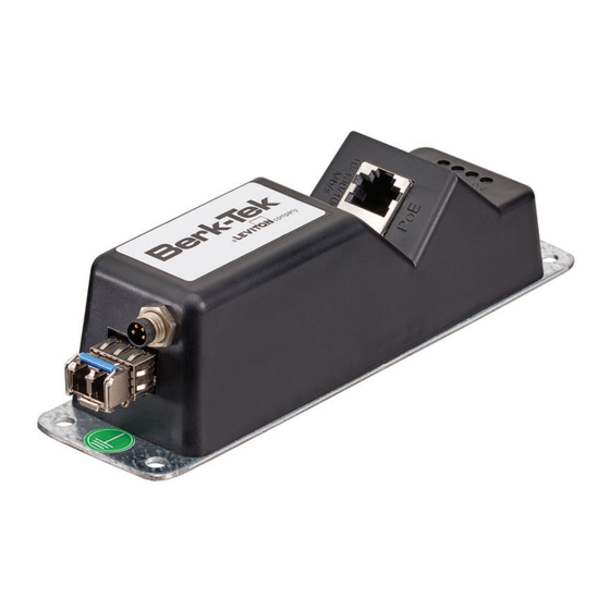
Ground Lead M8 Connector The installer must mount the OneReach units such that the base plates are connected to local ground. This is done by using grounding screws (not supplied) to secure the metal base of the PI source or remote to a mounting plate connected to an approved ground. -
Page 15: Surge Protection
Category cables running to the powered device as well as a high power grounded surge suppression device be installed at the source end of the hybrid cable. Specific installation guidelines are dependent on the surge protection device selected and the network design. See section 3.5 for a reference to a basic OneReach circuit diagram. - Page 16 1 800 405-5320. Patents covering this product, if any, can be found on Leviton.com/patents. Leviton and Leviton Block & Design are trademarks of Leviton Manufacturing Co., Inc. and are registered trademarks in many countries throughout the world. All other trademarks are the property of their respective owners and used for informational purposes only.
Need help?
Do you have a question about the OneReach and is the answer not in the manual?
Questions and answers