
Related Manuals for BERNSTEIN G30014A


Summary of Contents for BERNSTEIN G30014A
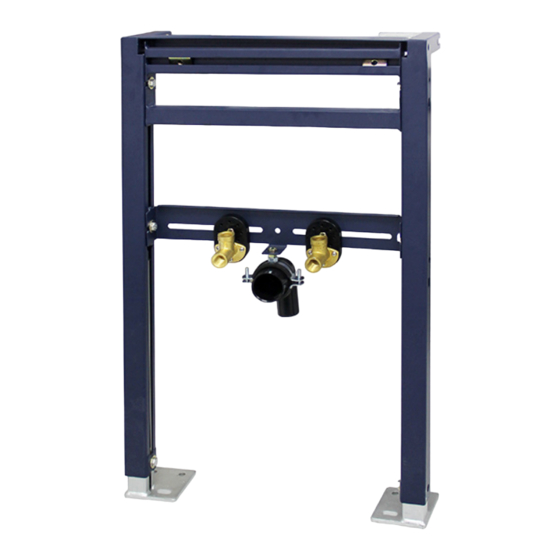
- Page 1 VORWANDELEMENT G30014A Waschtisch-Waschbecken MONTAGEANLEITUNG - II / 2020 ASSEMBLY INSTRUCTIONS / NOTICE DE MONTAGE / ISTRUZIONI DI MONTAGGIO...
- Page 2 VORWANDELEMENT G30014A Wandverstellschrauben x2 Wandhalterungen x2 Höhenverstellschrauben x2 Bodenhalterungen Einstellschrauben für die Verbindungshöhe x2 Verbindungsunterstützungsleiste x1 Warmwasseranschluss x1 Kaltwasseranschluss x1 Ablaufbogen x1 Gewindebolzen, Muttern und Unterlegscheiben zur Befestigung des Waschbeckens x2 Ablaufdichtung x1 Blindstopfen x2...
- Page 3 VORWANDELEMENT G30014A 135 mm - 205 mm Planen Sie die Position des Waschbeckens. Stellen Sie den Rahmen in der geplanten Position an die Die empfohlene Beckenhöhe-Oberkante beträgt 850 mm. Wand. Lösen Sie die Höhenverstellschrauben und stellen Der Abstand von der Wand kann vom Platzbedarf für einen Sie die gewünschte Höhe ein.
- Page 4 VORWANDELEMENT G30014A Langlöcher der Aufhängungen Rückseite des Waschbeckens Den Abstand ´X` zwischen den Mitten der Langlöcher Befestigen Sie Ablauf, Siphon und die Armatur am Becken. messen. Schrauben Sie die Gewindebolzen in die Hinweis: Es wird ein verstellbarer Abfluss mit Pop-Up Gleitplatten.
- Page 5 VORWANDELEMENT G30014A Lösen Sie die Zulaufanschlüsse für warm und kaltes Verbinden Sie die Zuläufe der Warm- und Kaltwasser- Wasser (mit der hinteren Mutter). Stellen Sie den leitungen mit den Anschlussbogen (Ø ½“). Schrauben Sie erforderlichen Abstand ein und ziehen Sie diese wieder fest.
- Page 6 VORWANDELEMENT G30014A Positionieren Sie das Becken vorsichtig auf die Gewinde- Befestigen Sie den Abfluss am Siphon und schieben Sie die bolzen und richten Sie den Ablauf aus. Setzen Sie die Abdeckung darüber. Kunststoff- und Metallscheiben unter dem Becken auf die Ziehen Sie alle Verbindungen fest an.
- Page 7 VORWANDELEMENT G30014A...
- Page 9 SUPPORT FRAME G30014A Wash basins ASSEMBLY INSTRUCTIONS - II / 2020 MONTAGEANLEITUNG / NOTICE DE MONTAGE / ISTRUZIONI DI MONTAGGIO...
- Page 10 SUPPORT FRAME G30014A Wall Adjustment Bolts x2 Wall Brackets x2 Height Adjustment Bolts x2 Floor Brackets Connection Height Adjustment Bolts x2 Connection Support Bar x1 Hot Water Inlet Elbow x1 Cold Water Inlet Elbow x1 Waste Outlet Elbow x1 Basin Fixing Bolts, Nuts & Washers x2...
- Page 11 SUPPORT FRAME G30014A 135 mm - 205 mm Plan the position of the basin. The recommended basin Place the frame against the wall in the required position. height is 850 mm to the front rim. The distance from the wall may depend on the space...
- Page 12 SUPPORT FRAME G30014A Basin fixing holes Back of basin Measure the distance ´X` between the centres of the basin Attach the waste, trap and mixer/tap, to the basin. fixing holes. Insert the basin fixing bolts into the sliding plates, position centrally on the frame and space apart to Note: A typical Bathstore adjustable chrome plated match the basin fixing holes.
- Page 13 SUPPORT FRAME G30014A Loosen the hot and cold inlet elbows (using the nut at the Connect the hot and cold pipework to the rear), set to the required distance apart and retighten. inlet elbows (Ø ½“), screw the blanking plugs into the outlets.
- Page 14 SUPPORT FRAME G30014A Secure the outlet pipe onto the trap and slide the cover up Carefully position the basin onto the fixing bolts, lining up to the wall. the waste connections at the same time. Fully tighten all connections. Under the basin, place the plastic and metal washers onto Remove the blanking plugs from the outlets.
- Page 15 SUPPORT FRAME G30014A...
Need help?
Do you have a question about the G30014A and is the answer not in the manual?
Questions and answers