
Related Manuals for BERNSTEIN G30013A


Summary of Contents for BERNSTEIN G30013A
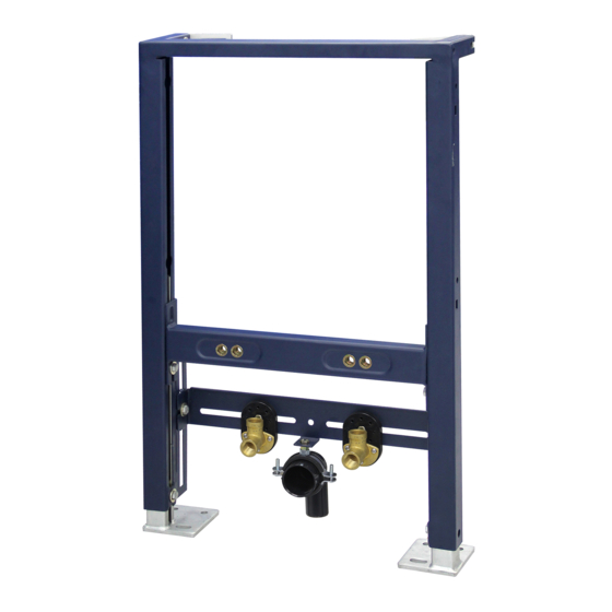
- Page 1 VORWANDELEMENT G30013A Bidet MONTAGEANLEITUNG - II / 2020 ASSEMBLY INSTRUCTIONS / NOTICE DE MONTAGE / ISTRUZIONI DI MONTAGGIO...
- Page 2 VORWANDELEMENT G30013A Wandverstellschrauben x2 Wandhalterungen x2 Höhenverstellschrauben x2 Bodenhalterungen x2 Einstellschrauben für die Verbindungshöhe x2 Verbindungsunterstützungsleiste x1 Warmwasseranschluss x1 Kaltwasseranschluss x1 Ablaufbogen x1 Trägerrahmen x1 Höhenverstellschrauben für die Bidetstützen x2 Gewindebolzen, Muttern, Unterlegscheiben und Abdeckungen x2 Querträger x1 Höhenverstellschrauben des Querträgers x2...
- Page 3 VORWANDELEMENT G30013A 135 mm - 205 mm Planen Sie die Position des Bidet. Stellen Sie den Rahmen in der geplanten Position an die Die empfohlene Beckenhöhe-Oberkante beträgt 400 mm. Wand. Lösen Sie die Höhenverstellschrauben und stellen Der Abstand von der Wand kann vom Platzbedarf für einen Sie die gewünschte Höhe ein.
- Page 4 VORWANDELEMENT G30013A Löcher der Aufhängungen Rückseite des Bidet Den Abstand ´X` zwischen den Mitten der Befestigungs- Befestigen Sie Siphon, Ablaufrohr und die Armatur am Bidet. öffnungen messen. Drehen Sie die Gewindebolzen in Hinweis: Es wird hier ein verstellbarer Abfluss mit Pop-Up die entsprechenden Löcher der Haltestange (innen oder...
- Page 5 VORWANDELEMENT G30013A Lösen Sie die Einstellschrauben der Querstangenhalterung. Lösen Sie die Zuläufe der Warm- und Kaltwasserleitungen Heben Sie die Querstangenstütze so hoch wie möglich an (mit den Muttern an der Rückseite). (unter den Ablaufbogen) und ziehen Sie beide Schrauben Stellen Sie den erforderlichen Abstand ein, um einen wieder fest.
- Page 6 VORWANDELEMENT G30013A X - 3mm Rohr kürzen Schieben Sie das Ablaufrohr bis zum Anschlag in den Messen Sie die markierte Länge des Ablaufrohrs (Xmm). Ablaufbogen. Legen Sie eine gerade Kante bündig an Dieser Betrag abzüglich 3mm ist die Endlänge des die Trennwand (wie abgebildet) und markieren Sie den Abflussrohrs und muss von der Rückseite des Bidet in den...
- Page 7 VORWANDELEMENT G30013A Zum Abschluß der Installation prüfen Sie die Anschlüsse auf ihre Dichtheit. Hinweis: Beziehen Sie bei der Planung, wenn möglich einen Revisionszugang mit ein.
- Page 9 SUPPORT FRAME G30013A Bidet ASSEMBLY INSTRUCTIONS - II / 2020 MONTAGEANLEITUNG / NOTICE DE MONTAGE / ISTRUZIONI DI MONTAGGIO...
- Page 10 SUPPORT FRAME G30013A Wall Adjustment Bolts x2 Wall Brackets x2 Height Adjustment Bolts x2 Floor Brackets x2 Connection Height Adjustment Bolts x2 Connection Support Bar x1 Hot Water Inlet Elbow x1 Cold Water Inlet Elbow x1 Waste Outlet Elbow x1...
- Page 11 SUPPORT FRAME G30013A 135 mm - 205 mm Plan the position of the bidet. The recommended bidet Place the frame against the wall in the required position. height is 400mm to the front rim. The maximum height Loosen the height adjustment bolts (and bidet support height...
- Page 12 SUPPORT FRAME G30013A Bidet fixing holes Back of bidet Measure the distance ‘X’ between the centres of the bidet Attach the trap, pop-up waste, waste pipe and mixer/tap, to fixing holes. Insert the bidet fixing bolts into the holes in the the bidet.
- Page 13 SUPPORT FRAME G30013A Loosen the cross bar support height adjustment bolts. Loosen the hot and cold inlet elbows (using the nut at the Raise the cross bar support up as high as possible (under rear). the waste outlet elbow) and retighten both bolts.
- Page 14 SUPPORT FRAME G30013A Measure the marked length of the ‘spare’ waste pipe (Xmm). Push fit a ‘spare’ section of waste pipe fully into the waste This measurement MINUS 3mm is the length of waste pipe outlet elbow. that is needed to extend from the back of the bidet into the Place a straight edge flush against the partition wall (as waste elbow.
- Page 15 SUPPORT FRAME G30013A Finish the installation by water testing the inlet and outlet connections and isolators in the void. Note: You must ensure there is access to the connections in the void. The installation is now completed by fitting the...
Need help?
Do you have a question about the G30013A and is the answer not in the manual?
Questions and answers