Table of Contents
Advertisement
Quick Links
SIMATIC
Bus link
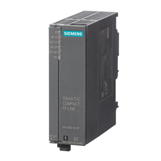
Compact FF Link
Operating Instructions
03/2015
A5E35651552-AA
Preface
Product overview
Description of the
components
Application planning
Mounting
Connecting
Commissioning
Operation of the bus link
Service and maintenance
Functions
Alarm, error, and system
messages
Technical data
Article numbers
1
2
3
4
5
6
7
8
9
10
11
12
A
Advertisement
Table of Contents

Related Manuals for Siemens SIMATIC Compact FF Link


Summary of Contents for Siemens SIMATIC Compact FF Link
- Page 1 Preface Product overview Description of the components SIMATIC Application planning Bus link Compact FF Link Mounting Connecting Operating Instructions Commissioning Operation of the bus link Service and maintenance Functions Alarm, error, and system messages Technical data Article numbers 03/2015 A5E35651552-AA...
- Page 2 Note the following: WARNING Siemens products may only be used for the applications described in the catalog and in the relevant technical documentation. If products and components from other manufacturers are used, these must be recommended or approved by Siemens. Proper transport, storage, installation, assembly, commissioning, operation and maintenance are required to ensure that the products operate safely and without any problems.
-
Page 3: Table Of Contents
Table of contents Preface.................................7 Security information.........................7 Preface.............................7 Product overview............................11 Integration in the automation landscape................11 Integrating Compact FF Link....................12 Description of the components........................13 Compact FF Link........................13 Active field distributor for connecting FF segments...............15 Application planning...........................17 Applications for Compact FF Link..................17 Configuration options......................17 Configuration variants of the Compact FF Link..............19 Single-channel connection of the Compact FF Link...............21 Redundant connection of the Compact FF Link..............21... - Page 4 Table of contents Commissioning............................41 Overview for commissioning the bus link ................41 Operation of the bus link..........................43 Startup/operation without CPU....................43 Startup with CPU........................44 Behavior after certain events in the redundancy mode............44 Startup behavior........................45 8.4.1 Startup behavior in non-redundant mode................46 8.4.2 Startup behavior in redundant mode..................47 Handling the quality code of cyclic data ................48 Service and maintenance...........................49 Replacing a bus link.......................49...
- Page 5 Table of contents 12.1.3 Electromagnetic Compatibility....................81 12.1.4 Shipping and storage conditions....................83 12.1.5 Mechanical and climatic ambient conditions for operation.............83 12.1.6 Specifications for insulation tests, protection class and degree of protection......85 12.1.7 Rated voltage.........................86 12.2 Technical Specifications Compact FF Link (6ES7655-5BA00-0AB0)........86 12.3 Technical specifications of active field distributors..............87 Article numbers............................89...
- Page 6 Table of contents Compact FF Link Operating Instructions, 03/2015, A5E35651552-AA...
-
Page 7: Preface
Siemens recommends strongly that you regularly check for product updates. For the secure operation of Siemens products and solutions, it is necessary to take suitable preventive action (e.g. cell protection concept) and integrate each component into a holistic, state-of-the-art industrial security concept. - Page 8 ● Ring redundancy with active field distributor (AFD..) You can find supplementary information on this in Operating Instructions DP/PA coupler, Active Field Distributor, DP/PA Link, and Y Link (http://support.automation.siemens.com/WW/view/ en/1142696). These operating instructions contain a description of the components that was valid at the time the operating instructions were published.
- Page 9 ● The system manual SIMATIC NET, PROFIBUS network manual (http:// support.automation.siemens.com/WW/view/en/35222591) ● PCS 7 documentation (http://www.siemens.com/pcs7-documentation) that describes the handling of the SIMATIC PCS 7 process control system, for example: PCS 7 Process Control System; Engineering System – Configuration Manual Process Control System PCS 7;...
- Page 10 Training Center Siemens offers a series of courses that will help you getting started with the components and the SIMATIC S7 and SIMATIC PCS 7 automation system. Please contact your regional training center or the central training center in D-90327, Nuremberg, Germany (http:// www.sitrain.com).
-
Page 11: Product Overview
Product overview Integration in the automation landscape Distributed I/O Devices - Field of Application When a system is configured, the inputs and outputs from and to the process are often integrated centrally in the automation system. In the case of greater distances of the inputs and outputs from the automation system, the wiring may be very extensive and confusing. -
Page 12: Integrating Compact Ff Link
Product overview 2.2 Integrating Compact FF Link The Compact FF Link is available for the transition of the transmission system from PROFIBUS DP to FF-H1 bus. Note Use in hazardous areas The Compact FF Link is approved only for use in Zone 2 hazardous areas. ●... -
Page 13: Description Of The Components
Description of the components Compact FF Link Functions ● Interface module (DPV1 slave) on the higher-level DP master system (in HW Config: IM 655‑5 FF) ● Field device coupler for a lower-level FF bus system (in HW Config: Field Device Coupler) ●... - Page 14 Description of the components 3.1 Compact FF Link Operating principle ● The Compact FF Link is a DPV1 slave on the higher-level DP master system and acts as a proxy for the nodes connected to the lower-level bus system (FF devices). A corresponding DP master is required for use of the Compact FF Link.
-
Page 15: Active Field Distributor For Connecting Ff Segments
Description of the components 3.2 Active field distributor for connecting FF segments In accordance with the FOUNDATION Fieldbus guideline (refer to section Standards and Approvals (Page 77)), each process variable is assigned a status byte that specifies the status of the process variable. When an FF device fails, the associated input data, including the status byte, is reset in the user data frame of the bus link. - Page 16 (Refer to the DP/PA coupler, Active Field Distributor, DP/PA Link, and Y Link (http://support.automation.siemens.com/WW/view/en/ 1142696) operating instructions. Up to 31 FF devices can be connected to an FF segment. ● The maximum current that the components on the FF segment require always depends on the bus link used.
-
Page 17: Application Planning
Application planning Applications for Compact FF Link The Compact FF Link is intended for the following applications: ● Single-channel operation on a non-redundant S7-4xxH or on a non-redundant DP master system (basic schematic in section "Single-channel connection of the Compact FF Link (Page 21)") ●... - Page 18 You can communicate with the FF devices via the Compact FF Link using Additional information can be found in Commissioning Manual Process Control System PCS 7, FOUNDATION Fieldbus (http://www.siemens.com/pcs7-documentation). In redundancy mode, all communication links from the PG / PC to the FF devices are retained at a switchover of the active Compact FF Link to the other Compact FF Link.
-
Page 19: Configuration Variants Of The Compact Ff Link
Application planning 4.3 Configuration variants of the Compact FF Link Configuration variants of the Compact FF Link Different configuration variants are possible with the Compact FF Link: ● Configuration with one Compact FF Link ● Configuration with two Compact FF Links Configuration variant with one Compact FF Link (configuration without FF Link Master redundancy) Configuration;... - Page 20 Application planning 4.3 Configuration variants of the Compact FF Link Reference For more detailed information about the configuration variants with Compact FF Link, refer to the following documents: Active field distributors ● Operating Instructions PCS 7 Process Control System, Fault-Tolerant Process Control ●...
-
Page 21: Single-Channel Connection Of The Compact Ff Link
Application planning 4.5 Redundant connection of the Compact FF Link Single-channel connection of the Compact FF Link Single-channel connection of the Compact FF Link of the FOUNDATION Fieldbus The following figure shows an example of the single-channel connection of the Compact FF Link with a non-redundant DP master system. - Page 22 Application planning 4.5 Redundant connection of the Compact FF Link Redundant connection of the Compact FF Link and coupler redundancy on the FOUNDATION Fieldbus The figure below shows an example of the redundant connection of Compact FF Link to a SIMATIC S7-410H or to a redundant DP master system.
- Page 23 Application planning 4.5 Redundant connection of the Compact FF Link Redundant connection of the Compact FF Link and ring redundancy on the FOUNDATION Fieldbus The figure below shows an example of the redundant connection of Compact FF Link to a SIMATIC S7-410H or to a redundant DP master system.
- Page 24 Application planning 4.5 Redundant connection of the Compact FF Link Compact FF Link Operating Instructions, 03/2015, A5E35651552-AA...
-
Page 25: Mounting
Additional instructions for installing modules in the S7 mounting system are available in Installation Manual Automation System S7-400, Hardware and Installation (http:// support.automation.siemens.com/WW/view/en/1117849): Mounting rules for active field distributors The information in this section is valid for the following active field distributors: ●... -
Page 26: Installing The Compact Ff Link
Mounting 5.3 Installing the Compact FF Link Mounting position The active field distributors can be installed in any orientation. Mounting system The active field distributors can be screw-mounted onto a flat, vibration-free surface with sufficient load bearing capacity. The modules can also be installed on a mounting rail using an adapter. - Page 27 Mounting 5.3 Installing the Compact FF Link Typical configuration The following figure shows the typical configuration of a bus link with a Compact FF Link when the front doors are open. Figure 5-1 Configuration of the bus link for single-channel operation Installing the bus link with a Compact FF Link 1.
-
Page 28: Installing The Compact Ff Link For Redundancy Mode
Mounting 5.3 Installing the Compact FF Link 5.3.2 Installing the Compact FF Link for redundancy mode Introduction The following configuration variants of the bus link with 2 Compact FF Links are possible for use of FF Link Master redundancy: ● Configuration with coupler redundancy See Redundant connection and coupler redundancy on the FOUNDATION Fieldbus (Page 21) ●... - Page 29 Mounting 5.3 Installing the Compact FF Link Typical configuration The following figure shows the typical configuration of a bus link with two Compact FF Links for redundancy mode with two power supply modules when the front doors are open. Figure 5-2 Typical configuration of a bus link for redundancy mode Installing the bus link for redundant mode 1.
-
Page 30: Setting The Profibus Address And Redundancy Mode
Mounting 5.4 Setting the PROFIBUS address and redundancy mode See also Accessories for PROFIBUS DP (Page 89) Accessories for FOUNDATION Fieldbus (Page 90) Setting the PROFIBUS address and redundancy mode Definition Each bus node must be assigned a PROFIBUS address for unambiguous identification on PROFIBUS DP. - Page 31 Mounting 5.4 Setting the PROFIBUS address and redundancy mode Procedure 1. Open the front panel of the Compact FF Link. 2. Set the desired PROFIBUS address using a screwdriver. If necessary, activate the ring redundancy. Example for setting the switch Notes PROFIBUS address The PROFIBUS address represents the sum of the values of...
- Page 32 Mounting 5.4 Setting the PROFIBUS address and redundancy mode Compact FF Link Operating Instructions, 03/2015, A5E35651552-AA...
-
Page 33: Connecting
Connecting Electrical isolation and grounding Introduction You can wire the 24 V power supply to the described modules depending on the requirements of your system configuration: ● Grounded configuration ● Ungrounded configuration Power supply The 24 V DC power supply is connected by a 2-pin connector from the bottom. You can find additional information on this in section "Connecting the power supply (Page 37)". -
Page 34: Connecting Compact Ff Link Without Redundancy
Connecting 6.2 Connecting Compact FF Link without redundancy Connecting Compact FF Link without redundancy 6.2.1 Wiring the Compact FF Link for non-redundant mode Connections of the Compact FF Link The figure below shows all connections you must establish from and to the Compact FF Link for non-redundant mode. -
Page 35: Connecting Compact Ff Link With Redundancy
Connecting 6.3 Connecting Compact FF Link with redundancy Connecting Compact FF Link with redundancy 6.3.1 Connecting Compact FF Link with coupler redundancy Connections of the bus link with coupler redundancy The following figure shows all connections you must establish for operation of the bus link with coupler redundancy on the FF bus. -
Page 36: Connecting Compact Ff Link With Ring Redundancy
Connecting 6.3 Connecting Compact FF Link with redundancy 6.3.2 Connecting Compact FF Link with ring redundancy Connections of the bus link with ring redundancy The following figure shows all connections you must establish for operation of the bus link with ring redundancy on the FF bus. -
Page 37: Wiring The Foundation Fieldbus To The Active Field Distributor
Connecting 6.4 Connecting the power supply See also Setting the PROFIBUS address and redundancy mode (Page 30) Connecting the power supply (Page 37) 6.3.3 Wiring the FOUNDATION Fieldbus to the active field distributor The information in this section is valid for the following active field distributors: ●... -
Page 38: Connecting Profibus Dp On Compact Ff Link
Connecting 6.5 Connecting PROFIBUS DP on Compact FF Link Wiring the power supply The 24 V DC incoming supply is located at the bottom of the module and is built with a two- pin male connector and a two-pin plug-in female connector. The female connector is inserted from below. -
Page 39: Connecting Foundation Fieldbus On Compact Ff Link
2. Tighten the fixing screws of the bus connector. Additional information All the information required for handling bus cables and connectors can be found in Manual ET 200 Distributed I/O System (http://support.automation.siemens.com/WW/view/en/ 1142470). Connecting FOUNDATION Fieldbus on Compact FF Link Important information The following content is binding for installation of the FOUNDATION Fieldbus: ●... - Page 40 Connecting 6.6 Connecting FOUNDATION Fieldbus on Compact FF Link FOUNDATION Fieldbus connection The 2-pin screw terminal for the FOUNDATION Fieldbus connection is located on the Compact FF Link behind the front door at the top . The connections have the following meaning: Bus termination for the FF segment when using active field distributors When using active field distributors, the bus is terminated automatically at the last bus node (automatic bus termination).
-
Page 41: Commissioning
Commissioning Overview for commissioning the bus link Requirements The following requirements must be met before you commission the bus link: ● PCS 7 (STEP 7) and SIMATIC PDM with "SIMATIC PDM Communication FOUNDATION Fieldbus" option package are installed on the engineering system. ●... - Page 42 Commissioning 7.1 Overview for commissioning the bus link Reference You can find information about the individual configuring and commissioning steps in Commissioning Manual Process Control System PCS 7, FOUNDATION Fieldbus (http:// www.siemens.com/pcs7-documentation). Compact FF Link Operating Instructions, 03/2015, A5E35651552-AA...
-
Page 43: Operation Of The Bus Link
Operation of the bus link Startup/operation without CPU Introduction You can download the FF bus parameters and LAS data (scheduler) to the bus link and the HW Config or SIMATIC PDM . The data is stored retentively there. Because FF devices using the FF parameter assignment is stored retentively in the Compact FF Link and the FF devices, the FOUNDATION Fieldbus starts up automatically after Power ON. -
Page 44: Startup With Cpu
Operation of the bus link 8.3 Behavior after certain events in the redundancy mode Startup with CPU Startup characteristics The following cases are distinguished: ● Once it is detected that all FF devices are available in accordance with the configuration, all output data is transferred and all input data is reported to the CPU. -
Page 45: Startup Behavior
Operation of the bus link 8.4 Startup behavior Startup behavior Requirement for startup of the bus link ● A valid PROFIBUS address is set on the Compact FF Link. ● The DP master on the higher-level PROFIBUS DP is in operation. ●... -
Page 46: Startup Behavior In Non-Redundant Mode
Operation of the bus link 8.4 Startup behavior 8.4.1 Startup behavior in non-redundant mode Startup characteristics The flow diagram below shows the startup behavior of the Compact FF Link after Power ON. Figure 8-1 Startup behavior of Compact FF Link after Power ON Compact FF Link Operating Instructions, 03/2015, A5E35651552-AA... -
Page 47: Startup Behavior In Redundant Mode
Operation of the bus link 8.4 Startup behavior 8.4.2 Startup behavior in redundant mode Startup diagram of the bus link with 2 Compact FF Links on SIMATIC S7 41xH The two Compact FF Links are addressed independently during startup: ● Each DP master configures and parameterizes its assigned Compact FF Link (independently of the other DP master) and sends the corresponding configuration. -
Page 48: Handling The Quality Code Of Cyclic Data
Operation of the bus link 8.5 Handling the quality code of cyclic data Handling the quality code of cyclic data Quality code of cyclic data During startup, the Compact FF Link initializes the I/O data for FF devices with "0" internally. This action also sets the quality code to "Bad". -
Page 49: Service And Maintenance
Service and maintenance Replacing a bus link Replacing a faulty Compact FF Link Perform the following steps to replace a faulty Compact FF Link. 1. Switch off the power supply for the faulty Compact FF Link. 2. Disconnect the faulty module from the power supply. 3. -
Page 50: Replacing Active Field Distributors
Service and maintenance 9.3 Firmware update of the Compact FF Link To prevent the lower-level FF segment from becoming inoperative, the Compact FF Links should be configured with independent switchable voltage supplies (e.g. by using two power supply modules). In redundancy mode, it is not necessary to load parameters to the new Compact FF Link if the other Compact FF Link is still running. -
Page 51: Restoring A Compact Ff Link Ff To The Factory State
Compact FF Links. Reference Instructions and the relevant firmware updates can be found at Internet (http:// support.automation.siemens.com/WW/view/en/10806836/133100). Select "Download" as the entry type for the search and "FF Link" as the search term. See also Service & Support (http://www.siemens.com/automation/service&support) -
Page 52: Maintenance
Service and maintenance 9.5 Maintenance 5. Set the correct PROFIBUS address. 6. Switch on the power supply. The Compact FF Link is operational again. Maintenance Maintenance The following components do not require any periodic maintenance: ● Power supply (provided that PS 307 is used) ●... -
Page 53: Functions
Functions 10.1 Redundancy with Compact FF Link Usage You can operate the bus link on a SIMATIC S7-400H redundantly (e.g. on CPU 410‑5H). Requirements ● Installation on BM Compact FF Link (active bus module for Compact FF Link) The bus module enables a fast switchover, when needed, thanks to the active communication between the two Compact FF Links. -
Page 54: Identification And Maintenance Data (I&M Data)
Functions 10.2 Identification and maintenance data (I&M data) See also Replacing a bus link (Page 49) 10.2 Identification and maintenance data (I&M data) Definition and features Identification and maintenance data (I&M) is information stored in a module to support you in ●... -
Page 55: System Modification During Operation
Information regarding the complete procedure for a system modification and related requirements can be found in the following documentation: ● Modifying the system during operation via CiR (http://support.automation.siemens.com/ WW/view/en/14044916) ● Firmware update of the Compact FF Link (Page 50) ● S7-400H Fault-Tolerant Systems (http://support.automation.siemens.com/WW/view/en/... -
Page 56: Control In The Field (Cif)
(see section Startup behavior in non-redundant mode (Page 46)). Reference For more information about "Control in the Field", refer to Commissioning Manual Process Control System PCS 7, FOUNDATION Fieldbus (http://www.siemens.cm/pcs7- documentation). Compact FF Link Operating Instructions, 03/2015, A5E35651552-AA... -
Page 57: Alarm, Error, And System Messages
Alarm, error, and system messages 11.1 Diagnostics using LEDs 11.1.1 LEDs of the Compact FF Link Tables for the status and error messages of the Compact FF Link can be found in the following: ● Status and error messages of the Compact FF Link (not redundant) ●... - Page 58 Alarm, error, and system messages 11.1 Diagnostics using LEDs Status and error messages of the Compact FF Link (not redundant) LEDs Meaning Solution BF FF ACT FF BF DP ACT DP ● No voltage is applied to the ● Switch on the Compact FF Link.
- Page 59 Alarm, error, and system messages 11.1 Diagnostics using LEDs LEDs Meaning Solution BF FF ACT FF BF DP ACT DP Flash‐ The FF segment is overloaded (flashing Check the number of es slow‐ frequency of 0.2 Hz). connected FF devi‐ ces and their total cur‐...
- Page 60 Alarm, error, and system messages 11.1 Diagnostics using LEDs Status and error messages of the redundant Compact FF Link LEDs Meaning Solution BF FF ACT FF BF DP ACT DP Redundancy: Active channel (Good sta‐ tus) The Compact FF Link is exchanging da‐ ta between the DP master and the low‐...
- Page 61 Alarm, error, and system messages 11.1 Diagnostics using LEDs LEDs Meaning Solution BF FF ACT FF BF DP ACT DP Flash‐ After startup: es rap‐ The Compact FF Link is starting up (see idly section "Startup behavior (Page 45)"). Downloading of DP parameters is com‐ plete.
-
Page 62: Leds Of The Active Field Distributors
FF device on the FOUNDATION Fieldbus. Additional information can be found in Commissioning Manual Process Control System PCS 7, FOUNDATION Fieldbus (http://www.siemens.com/pcs7-documentation). Diagnostic address The diagnostic address of the Compact FF Link is assigned automatically in PCS 7. You can find the diagnostic address on the "General"... - Page 63 Alarm, error, and system messages 11.2 Diagnostics of the Compact FF Link of 31 slots. The assignment of the virtual slots for diagnostic communication when using the Compact FF Link is as follows: ● Slot 0 The Compact FF Link occupies slot 0. This also applies in redundant operation with 2 Compact FF Links (IM 655-5 FF).
-
Page 64: Structure Of Slave Diagnostics
For additional information, please refer to the hardware" For more information on reading out diagnostics information, refer to the Programming with STEP 7 (http://support.automation.siemens.com/WW/view/en/18652056) manual. See also Structure of slave diagnostics (Page 64) Reading out diagnostics from FF devices (Page 75) Interrupts (Page 73) 11.2.1... -
Page 65: Structure Of The Diagnostic Blocks
Alarm, error, and system messages 11.2 Diagnostics of the Compact FF Link Diagnostic blocks in S7 standard mode and in the redundancy mode The table below shows the lengths of the diagnostics blocks and their offset in the diagnostics frame. Table 11-1 Length and offset of the diagnostic blocks in S7 standard mode and in redundancy mode Diagnostic block... - Page 66 Alarm, error, and system messages 11.2 Diagnostics of the Compact FF Link Station statuses 1 to 3 Station status 1 to 3 provides an overview of the state of the Compact FF Link FF. Table 11-2 Format of station status 1 Meaning Cause / remedy 1: The Compact FF Link FF cannot be addressed by the...
-
Page 67: Identifier-Related Diagnostics
Alarm, error, and system messages 11.2 Diagnostics of the Compact FF Link Table 11-4 Format of station status 3 Meaning 0 to 7 0: Bits are always set to "0". Master PROFIBUS address The PROFIBUS address of the specific DP master that configured the Compact FF Link FF and that has reading and writing access to the Compact FF Link FF is stored in byte 3 of the default diagnostics. - Page 68 Alarm, error, and system messages 11.2 Diagnostics of the Compact FF Link Example of slot assignment Figure 11-2 Example of slot assignment Format of the identifier-related diagnostics The identifier-related diagnostics comprises 6 bytes. The Compact FF Link and each FF device occupy one bit. The FF devices are arranged in ascending order according to their FF addresses.
-
Page 69: Module Status
Alarm, error, and system messages 11.2 Diagnostics of the Compact FF Link One bit is set: ● If the Compact FF Link has received non-matching DP and FF configuration data Note This state can occur temporarily with CiR processes. It is only necessary to take steps if the error persists. - Page 70 Alarm, error, and system messages 11.2 Diagnostics of the Compact FF Link The following applies to the entry in the module status: ● For the Compact FF Link: – 00 : Compact FF Link is OK – 01 : External error, PROFIBUS address differs from the one used at startup; the redundant Compact FF Link has a different PROFIBUS address –...
-
Page 71: Status Message
Alarm, error, and system messages 11.2 Diagnostics of the Compact FF Link 11.2.2.4 Status message Definition The status message is part of the device-related diagnostics and supplies the assignment of slots to the configured FF device addresses. As soon as the configuration information is available in the Compact FF Link, and the Compact FF Link switches to data exchange, the data is updated. - Page 72 Alarm, error, and system messages 11.2 Diagnostics of the Compact FF Link Format of the H status Figure 11-6 Format of the H status of the Compact FF Link FF in redundancy mode Compact FF Link Operating Instructions, 03/2015, A5E35651552-AA...
-
Page 73: Interrupts
Alarm, error, and system messages 11.3 Interrupts 11.3 Interrupts Definition The interrupt section provides information on the type of interrupt and the cause leading to the interrupt being triggered. The interrupt section is only transmitted if there is an interrupt. The interrupt part consists of a maximum of 63 bytes. - Page 74 Alarm, error, and system messages 11.3 Interrupts Table 11-6 Interrupt type (bytes x+1 in the interrupt section) Byte x+1 Interrupt type Byte x+1 Interrupt type Reserved Status interrupt Diagnostic interrupt Update interrupt Process interrupt to 1F Reserved Pull interrupt to 7E Manufacturer-specific interrupt Plug interrupt Reserved...
-
Page 75: Reading Out Diagnostics From Ff Devices
Non-cyclic diagnostics is also possible SIMATIC PDM . by means of Reference For more information about the diagnostics of FF devices, refer to the PCS 7 Process Control System, FOUNDATION Fieldbus (http://www.siemens.cm/pcs7-documentation) Commissioning Manual. See also The Process Device Manager (http://support.automation.siemens.com/WW/view/en/... - Page 76 Alarm, error, and system messages 11.4 Reading out diagnostics from FF devices Compact FF Link Operating Instructions, 03/2015, A5E35651552-AA...
-
Page 77: Technical Data
Technical data 12.1 General technical data What are general technical specifications? The technical specifications contain: ● The standards and test values that observe and fulfil the described components. ● The test criteria used to test the described components. 12.1.1 Standards and Approvals Standards and Approvals The components described meet the following standards and approvals. - Page 78 DE‑90475 Nuremberg Germany The EC Declaration of Conformity is also available for download from the Internet (http:// www.siemens.com/automation/service&support) (keyword "Declaration of Conformity"). ATEX Approval DEKRA 14ATEX 0026 X According to EN 60079‑15 (Electrical apparatus for potentially explosive atmospheres; Type of protection "n") and EN 60079-0 (Explosive atmospheres; General requirements) WARNING Personal injury and material damage can be incurred.
- Page 79 Technical data 12.1 General technical data According to IEC 60079-15 (Explosive atmospheres - Part 15: Equipment protection by type of protection "n") and IEC 60079-0 (Explosive atmospheres - Part 0: Equipment - General requirements) WARNING Personal injury and material damage can be incurred. In potentially explosive atmospheres, personal injury and material damage can be incurred if plug connections are disconnected during operation.
- Page 80 Technical data 12.1 General technical data WARNING Installation Instructions according cULus WARNING – Explosion Hazard - Do not disconnect while circuit is live unless area is known to be non-hazardous. WARNING – Explosion Hazard - Substitution of components may impair suitability for Class I, Division 2 or Class I, Zone 2 This equipment is suitable for use in Class I, Division 2, Groups A, B, C or D;...
-
Page 81: Use In Zone 2 Potentially Explosive Areas
● Use of interference filters in the supply lines 12.1.2 Use in zone 2 potentially explosive areas See product information Using the modules in the hazardous zone 2 (http:// support.automation.siemens.com/WW/view/en/19692172). 12.1.3 Electromagnetic Compatibility Introduction This chapter provides you with information on the immunity to interference of the described components as well as on radio interference suppression. - Page 82 IEC 61000‑4‑5 External protective circuit needed (refer to the Automation System S7-400, Hardware and Installation Lightning (http://support.automation.siemens.com/WW/view/en/1117849) Installation Manual, chapter protection and overvoltage protection ) It is not necessary to install an external protection circuit for the FF bus. 2 kV (supply line) ●...
-
Page 83: Shipping And Storage Conditions
Technical data 12.1 General technical data 12.1.4 Shipping and storage conditions Transport and Storage of Modules The components described surpass the requirements for transport and storage conditions according to the following standard: IEC 61131 Teil 2. The following information applies to modules transported or stored in their original packaging. Type of condition Permitted range Free fall (in transport packaging) - Page 84 Technical data 12.1 General technical data Mechanical ambient conditions The mechanical ambient conditions for the described components are specified in the table below for sinusoidal vibrations. Frequency range in Hz Continuous Infrequently 10 ≤ f ≤ 58 0.0375 mm amplitude 0.075 mm amplitude g constant acceleration g constant acceleration...
-
Page 85: Specifications For Insulation Tests, Protection Class And Degree Of Protection
Technical data 12.1 General technical data Ambient conditions Permitted range Remarks Relative humidity from 10 to 95 % Without condensation, corresponds to relative humidity (RH) stress class 2 in accordance with IEC 61131-2 With condensation: Active field distributors DP/PA coupler, Ac‐ See Operating Instructions tive Field Distributor, DP/PA Link and Y Link Atmospheric pressure... -
Page 86: Rated Voltage
Technical data 12.2 Technical Specifications Compact FF Link (6ES7655-5BA00-0AB0) 12.1.7 Rated voltage Rated voltage for operation The described components work with a rated voltage of 24 V DC. The tolerance range extends from 20.4 V DC to 28.8 V DC. Exceptions ●... -
Page 87: Technical Specifications Of Active Field Distributors
Technical data 12.3 Technical specifications of active field distributors Min. 5 ms ● Power failure bypass Output current FF section: (for dimensioning the FF configuration) 500 mA (depending on mounting position) ● Up to 70° C ambient temperature Max. 8 W ●... - Page 88 Technical data 12.3 Technical specifications of active field distributors Compact FF Link Operating Instructions, 03/2015, A5E35651552-AA...
-
Page 89: Article Numbers
Active field distributors Refer to the Operating Instructions DP/PA (Active Field Distributor and Active Field Splitter) coupler, Active Field Distributor, DP/PA Link, and Y Link (http:// support.automation.siemens.com/WW/view/ en/1142696) Accessories for installation Component Article number Mounting rail "for standard configuration" e.g. -
Page 90: Accessories For Foundation Fieldbus
Article numbers A.3 Accessories for FOUNDATION Fieldbus Accessories Article number ● with PG socket 6ES7972‑0BB12‑0XA0 PROFIBUS DP bus connector RS485 with 90° cable outlet for FastConnect connection system, max. transmission rate 12 Mbps 6ES7972‑0BA52‑0XA0 ● without PG socket 6ES7972‑0BB52‑0XA0 ● with PG socket PROFIBUS FastConnect bus cable 6XV1830-0EH10 ●... -
Page 91: Glossary
Glossary Address The address of a node is used for locating it in the network. It has to be unique in the entire network. Aggregate current Aggregate current of all PA or FF field devices. Automation system An automation system is a programmable control system, consisting of at least one CPU, various input and output modules as well as operating and monitoring devices. - Page 92 Glossary Diagnostics Diagnostics is the detection, localization, classification, display and further evaluation of errors, faults and messages. Diagnostics provides monitoring functions that run automatically while the plant is in operation. This increases the availability of plants by reducing commissioning times and downtimes. DP master A master that behaves in conformity with IEC 61784‑1 CP 3/1 is termed a DP master.
- Page 93 Glossary ● Fieldbus Foundation ● OPC Foundation The EDDL (Electronic Device Description Language) is used as basis for the device descriptions. Electromagnetic compatibility Electromagnetic compatibility is the capacity of electrical equipment to function faultlessly in a specified environment without affecting the environment in an inadmissible manner. Equipment, associated A piece of electrical equipment that contains both intrinsically safe and non-intrinsically safe power circuits and is configured so that the non-intrinsically safe power circuits cannot impede...
- Page 94 Glossary FF Link Master A master that behaves in conformity with IEC 61784‑1 CP 1/1 is termed a FOUNDATION Fieldbus Link Master. The bus link (Compact FF Link) acts as a DP slave for "higher-level" systems (toward the automation system) and as an FF Link Master for "lower-level" systems (toward the FF devices).
- Page 95 Glossary HW Config STEP 7 for configuring hardware. Integral part of Identification and maintenance data Identification data (I data) is information on the module, some of which are printed onto the module housing. I data are for reading only. Maintenance data (M data) is plant-dependent information such as installation location, installation date etc.
- Page 96 Glossary PROFIBUS PROcess FIeld BUS, process and fieldbus standard as specified in IEC 61784-1 CPF 3 PROFIBUS and PROFINET. It specifies functional, electrical, and mechanical properties for a bit-serial field bus system. PROFIBUS is available with the protocols: DP (=distributed I/O) and FMS (= Field bus Message Specification) PROFIBUS address Each bus node must be assigned a PROFIBUS address for unambiguous identification on...
- Page 97 Glossary SELV Safety extra low voltage (SELV) is voltage < 30 V AC / 60 V DC that is generated by means of safety transformer, accumulator etc. SIMATIC PDM SIMATIC PDM (Process Device Manager) is an integrated, vendor-neutral tool used for configuring, parameter assignment, commissioning and diagnosing intelligent process SIMATIC PDM makes it possible to configure a large variety of process devices with devices.
- Page 98 Glossary Update After (compatible) functional upgrades or improvements to performance you should update the Compact FF Link to the most recent firmware version in each case. Compact FF Link Operating Instructions, 03/2015, A5E35651552-AA...
-
Page 99: Index
Index Non-redundant, 21 Overvoltage protection, 49 Properties, 13 Replacing, 49 Accessories Special features, 20 for FOUNDATION Fieldbus, 90 Technical specifications, 86 for PROFIBUS DP, 89 Compact FF Link Active Field Distributor, 15 Configuration variants, 19 Active Field Splitter, 15 Components AFD..., 15 Accessories, 89 AFS, 15... - Page 100 Index Field distributors Grounding, 16 Mounting position, 26 Mounting system, 26 Power supply Properties, 16 Wiring, 37 FM approval, 80 PROFIBUS address FOUNDATION Fieldbus Setting, 30 Commissioning guideline, 39 PROFIBUS address of the DP master, 67 Wiring, 39 PROFIBUS DP Wiring to Compact FF Link, 39 Properties Compact FF Link, 13...
- Page 101 Index Startup characteristics Bus link in non-redundant mode, 46 Bus link in redundancy mode, 47 Station status, 66 Status message, 71 Switch RING, 30 Technical Support, 10 Test voltages, 85 Training Center, 10 Type of protection IP30, 85 Vibrations, 84 Compact FF Link Operating Instructions, 03/2015, A5E35651552-AA...
- Page 102 Index Compact FF Link Operating Instructions, 03/2015, A5E35651552-AA...
Need help?
Do you have a question about the SIMATIC Compact FF Link and is the answer not in the manual?
Questions and answers