Table of Contents
Advertisement
Quick Links
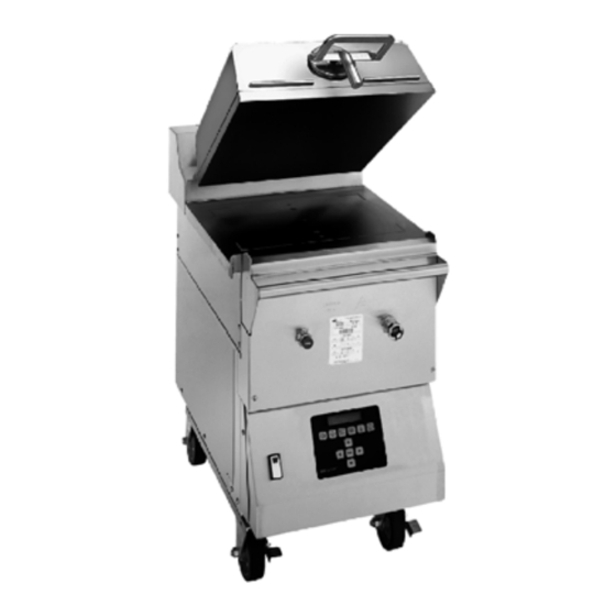
Clamshell Grill
Models C836 & C838
Place this chapter in the Grill section
of the Equipment Manual.
Manufactured exclusively for
McDonald's® by
Taylor Company
750 N. Blackhawk Blvd.
Rockton, IL 61072
Phone: (815) 624-8333
Toll Free Number
Outside Illinois:
1 (800) 228-8309
Inside Illinois:
1 (800) 851-5639
Fax: (815) 624-8000
Table of Contents
. . . . . . . . . . . . . . . . . . . . . . . . . . . . . . . . . . . . . . . . . . . . . . . . . . . . .
. . . . . . . . . . . . . . . . . . . . . . . . . . . . . . . . . . . . . . . . . . . . . . . . . . . . . . . . . .
. . . . . . . . . . . . . . . . . . . . . . . . . . . . . . . . . . . . . . . . . . . . . . . . . . .
. . . . . . . . . . . . . . . . . . . . . . . . . . . . . . . . . . . . . . . . . . . . . . . . . . .
. . . . . . . . . . . . . . . . . . . . . . . . . . . . . . . . . . . . . . . . . . . . . . . . . . . . .
. . . . . . . . . . . . . . . . . . . . . . . . . . . . . . . . . . . . . . . . . . . . . . . . . . . .
. . . . . . . . . . . . . . . . . . . . . . . . . . . . . . . . . . . . . . . . . . . . . . . . . .
Warranty
Warranty information is contained in this Equipment Manual. Refer to the warranty information listed in the Limited
Warranty on Equipment and Limited Warranty on Parts sections and to the warranty classifications listed in the Parts
Identification/Function section when service is performed on your machine.
It is recommended that the operator take the necessary time to carefully read through the complete warranty information.
Thoroughly understand your warranty protection before you begin operation.
For any questions pertaining to the Taylor Warranty, please contact Taylor Company, Rockton, Illinois 61072.
This manual is for the exclusive use of licensees and employees of McDonald's Corporation.
E2014 McDonald's Corporation
All Rights Reserved
. . . . . . . . . . . . . . . . . . . . . . . . . . . . . . . . . . . . . . .
. . . . . . . . . . . . . . . . . . . . . . . . . . . . . . . . . . . . . . . . .
. . . . . . . . . . . . . . . . . . . . . . . . . . . . . . . . . . . . .
. . . . . . . . . . . . . . . . . . . . . . . . . . . . . . . . . . . . . . . .
. . . . . . . . . . . . . . . . . . . . . . . . . . . . . . . . . . . . . . . . . . . .
. . . . . . . . . . . . . . . . . . . . . . . . . . . . . . . . . . . .
. . . . . . . . . . . . . . . . . . . . . . . . . . . . . . . . . . . . . . . . .
. . . . . . . . . . . . . . . . . . . . . . . . . . . . . . . . . . . . . .
. . . . . . . . . . . . . . . . . . . . . . . . . . . . . . . . . . . . . .
June, 2014 (Original Publication)
(Updated February, 2015)
EM SD11
Page 1
Page 1
Page 4
Page 10
Page 12
Page 16
Page 23
Page 39
Page 42
Page 44
Page 47
Page 48
Page 48
Page 53
Page 61
Page 62
Printed in
The United States of America
Advertisement
Table of Contents

Related Manuals for McDonald's C836


Summary of Contents for McDonald's C836
-
Page 1: Table Of Contents
Thoroughly understand your warranty protection before you begin operation. For any questions pertaining to the Taylor Warranty, please contact Taylor Company, Rockton, Illinois 61072. This manual is for the exclusive use of licensees and employees of McDonald's Corporation. E2014 McDonald's Corporation... -
Page 3: Introduction
INTRODUCTION This unit is to be used only by trained The Model C836 and C838 grills have one personnel. It is not intended for use by independent upper platen. The grills provide children or people with reduced physical, automatic leveling of the platen. They are... - Page 4 Stationary appliances which are not equipped with a power cord and a plug or other device to disconnect the This appliance must be isolated from appliance from the power source must all combustible construction and have an all-pole disconnecting device materials including, but not limited to;...
- Page 5 NOISE LEVEL: Airborne noise emission does not exceed 70 dB(A) when measured at a distance of 1.0 meter from the surface of the The grill must be placed on a level machine and at a height of 1.6 meters from surface.
-
Page 6: Parts Identification/Function
PARTS IDENTIFICATION/FUNCTION C836 Exploded View (See Figure 1.) ITEM TAYLOR DESCRIPTION QTY. FUNCTION WARR. PART NO. CLASS 074110 Panel-Side Left Provides access to internal com- ponents for service and cleaning. 024298 Screw-10-32 X 3/8 Secures the panel to the frame. - Page 7 C836 Exploded View Figure 1 © 2015 Carrier Commercial Refrigeration, Inc. 150209...
- Page 8 C838 Exploded View (See Figure 2.) ITEM TAYLOR DESCRIPTION QTY. FUNCTION WARR. PART NO. CLASS 073345-L Panel-Side Left Provides access to internal com- ponents for service and cleaning. 039381 Screw-10-32 X 3/8 Secures the panel to the frame. 073352 Panel-Side Upper Left Provides access to internal com- ponents for service and cleaning.
- Page 9 C838 Exploded View Figure 2 © 2015 Carrier Commercial Refrigeration, Inc. 150209...
- Page 10 C836 / C838 Front View ITEM TAYLOR DESCRIPTION QTY. FUNCTION WARR. PART NO. CLASS 076989-WP Switch-Rocker-DPST Activates power to the grill and the 10A (Fan Interlock) exhaust fans. 076011 Button-Operator-Red Cancels the Standby mode, raises (Raise) the upper platen, and deactivates the Cook cycle.
- Page 11 C836 / C838 Accessories ITEM TAYLOR DESCRIPTION QTY. FUNCTION WARR. PART NO. CLASS 073317 Sheet-Release Non-stick barrier used to protect (Box of 6) the upper platen. 076155 Rod-Release Material Slides through the loop in the release material sheet. 072673 Clip-Release Material...
-
Page 12: Important To The Operator
IMPORTANT TO THE OPERATOR Important to the Operator Exploded View (See Figure 5.) ITEM DESCRIPTION FUNCTION Fan Interlock Switch This switch activates power to the grill and the exhaust fans. ON/OFF Key This key is used to turn the controller on and off to start a preheating mode and to auto-gap the platen. - Page 13 Important to the Operator Figure 5 Symbol Definitions To better communicate in the International arena, the words on many of our operator = PROGRAM keys have been replaced by symbols to indicate their functions. Your Taylor equipment is designed with these International symbols. = TEMPERATURE The following chart identifies the symbol definitions.
-
Page 14: Equipment Set Up Procedures
EQUIPMENT SET-UP PROCEDURES Installing Upper Platen Release Sheet 1. Slide the release material retention bar through the loop in the release sheet. (See Figure 6.) Figure 8 4. Carefully wrap the release sheet side flaps over the cover rails and secure the sheet with locking clips. - Page 15 Installing Lower Release Sheet 4. The screen will then display, “CLEAN (Grills Using a Lower Release Sheet) GRILL SURFACES,” followed by “CLOSE PLATEN FOR AUTO LEVELING.” Note: The following steps pertain to grill 5. Using a sundae spoon, distribute two level markets using a lower release sheet, only.
- Page 16 8. With the longest side of the lower release 10. Press the Standby button to close the sheet facing the back of the grill, hold the platen. (See Figure 17.) release sheet about 1/2 inch from the end of each side. Align the back edge of the release sheet with the back splash and the side edge of the grill.
- Page 17 Start-Up of the Grill 3. The control will first display, “CLEAN GRILL SURFACES” and then display, IMPORTANT: The lower grill plate and the “CLOSE PLATEN FOR AUTO upper platen MUST BE CLEAN before starting LEVELING.” these procedures. 4. Press the Standby button to close the Note: Grills that use a lower release sheet platen.
-
Page 18: Menu Screens
Manager Menu - Passcode Access MENU SCREENS The Manager Menu gives access to all MENU Limited access to menu screens is available items and limited SYSTEM SETUP access. To through the Operator and Manager Menus. In order to enter the Operator Menu or the Manager Menu, individual passcodes must be access the Manager Menu, press the entered. - Page 19 Product Selection Patty Placement Placement procedures of meat products must be followed on the grill. Meat must be placed key allows the operator to cook in either the AUTO mode or in the MANUAL on the lower grill plate, two patties at a time, from front to back, per the patty placement mode.
- Page 20 Model C836 & C838 IntelliGapt Grill 10:1, 4:1, Sausage, Circular Bacon, and Patty Placement Guide Figure 21 Note: Patty placement procedures for International Markets may differ. Follow the recommendations of your local McDonald's authorities. 150209...
- Page 21 Standby Procedures Cleaning After Each Run of Product (Grills Using a Lower Release Sheet) Whenever the grill is idle and product is not being cooked, the upper platen must be placed in the STANDBY position. Note: This manual contains separate procedures for grills that use a lower release 1.
- Page 22 4. Carefully squeegee the air bubbles from 2. Use the wiper squeegee to clean the center to side, making sure the release release sheet on the upper platen. Use a sheet does not become folded or creased. diagonal motion to clean the sheet. Hold the handle at a slight upward angle, with 5.
- Page 23 To Cook in the Flat Grill Mode To Transition From Breakfast to Lunch 1. If the grill is in the AM AUTO Mode, press 1. To select a flat grill menu item, press the key to select PM. key. 2. If the grill is set to a certain breakfast item in the Manual Mode, press the to select PM.
- Page 24 Measurements should be taken from front to back. The illustrations below identify the probe locations. C836 To Change Product Cook Times 1. Press the key to put the grill into the Manual Mode.
-
Page 25: Daily Cleaning Procedures
Probe Calibration (continued) DAILY CLEANING PROCEDURES Grills Using a Lower Release Sheet 1. Press the key to put the grill into the Note: This manual contains separate Manual Mode. procedures for grills that use a lower release sheet and for grills that do not use a lower release sheet. - Page 26 2. Press the key until the message CAUTION: THE UPPER PLATEN, “CLEANING” is displayed LOWER COOK SURFACE AND RELEASE SHEETS ARE VERY HOT. TO PREVENT BURN INJURIES, USE EXTREME CARE. 3. Press the key. When the cook surfaces reach the proper 8.
- Page 27 10. Dip a clean, sanitizer-soaked grill cloth 13. Place the release sheets flat on the into the grill cleaner. Do not saturate the release sheet storage tray. DO NOT fold, cloth. (See Figure 36.) crease, or place them on sharp objects. DO NOT clean the release sheets in the 3-compartment sink.
- Page 28 16. Apply McD Hi-Temp Grill Cleaner 19. Apply the grill cleaner to the left side of (HTGC) to the front side of the platen. the platen. (See Figure 44.) (See Figure 41.) Figure 44 20. Apply grill cleaner to the right side of the Figure 41 platen.
- Page 29 22. Scrub the platen surfaces. 25. Scrub the right side of the platen. (See Figure 47.) (See Figure 50.) Figure 50 Figure 47 26. Rinse all areas of the platen surface with 23. Scrub the back side of the platen. a clean, sanitizer-soaked grill cloth.
- Page 30 28. Clean the surrounding areas such as the 30. Re-install the upper release sheet. Secure hood, bull nose, and back splash with a the sheet with the locking clips and bars. clean, sanitizer-soaked grill cloth. (See Figure 55.) (See Figure 53.) Figure 55 Note: Reverse the cooking side of the release sheet on a daily basis (example:...
- Page 31 33. Wash and rinse the grease pans in the 38. Using a clean squeegee, spread the 3-compartment sink. flakes on the cooking zone. (See Figure 60.) 34. Re-install the grease pans. (See Figure 58.) Figure 58 Figure 60 39. With the longest side of the lower release 35.
- Page 32 40. Gently squeegee the air bubbles and Cleaning Procedure - 24 Hour Stores Only wrinkles out of the release sheet. Do not (Grills Using a Lower Release Sheet) crease or fold the release sheet. (See Figure 62.) 1. Clean the grill using the Daily Cleaning Procedures on pages 23 - 30, steps 1 - 40.
- Page 33 DAILY CLEANING PROCEDURES 2. Press the key until the message “CLEANING” is displayed Grills Not Using a Lower Release Sheet IMPORTANT: This manual contains separate procedures for grills that use a lower release 3. Press the key. sheet and for grills that do not use a lower release sheet.
- Page 34 7. Wipe the exposed surface of the release 9. Set the release sheet aside on a clean, sheet with a clean, sanitizer-soaked grill flat surface until further cleaning is cloth. (See Figure 66.) performed. Do not fold, crease, or place it on sharp objects.
- Page 35 12. Remove, empty, and reinstall the grease IMPORTANT: DO NOT scrub while applying pans. (See Figure 71.) the grill cleaner in the following steps: 15. Apply McD Hi-Temp Grill Cleaner (HTGC) to the front side of the platen. (See Figure 74.) Figure 71 13.
- Page 36 17. Apply the grill cleaner to the back side of 20. Using the Kay Grill Cleaning Pad Holder, the platen. (See Figure 76.) scrub the front side of the platen. (See Figure 79.) Figure 76 Figure 79 18. Apply the grill cleaner to the left side of 21.
- Page 37 23. Scrub the left side of the platen. 26. Rinse the right side of the platen with a (See Figure 82.) clean, sanitizer-soaked grill cloth. (See Figure 85.) Figure 82 Figure 85 24. Scrub the right side of the platen. 27.
- Page 38 29. Spread a light coating of the grill cleaner 31. Pour a small amount of lukewarm water over the entire lower grill surface, using on a clean, sanitizer-soaked grill cloth front to back strokes. Do not scrub while while holding it over the bottom grill applying cleaner.
- Page 39 34. Re-install the release sheet. Secure the 37. Wash and rinse the grease pans in the sheet with the locking clips and bars. 3-compartment sink. (See Figure 93.) 38. Re-install the grease pans. (See Figure 96.) Figure 93 Note: Reverse the cooking side of the release sheet on a daily basis (example: Figure 96 black side on odd days;...
- Page 40 Cleaning Procedure - 24 Hour Stores Only Note: Reverse the cooking side of the (Grills Not Using a Lower Release Sheet) release sheet on a daily basis (example: black side on odd days; grey or brown 1. Clean the grill using the Daily Cleaning side on even days).
-
Page 41: Troubleshooting Guide
TROUBLESHOOTING GUIDE WARNING: Inspection, testing, and DANGER: Use extreme care during repair of electrical equipment should be electrical circuit tests. Live circuitry may performed only by qualified service be exposed. personnel. The grill must be pulled away from the wall for thorough cleaning. When returning the The grill should be disconnected grill to its original position, use extreme from all electricity when servicing, except... - Page 42 PROBLEM PROBABLE CAUSE REMEDY The exhaust hood alone does The fan interlock switch is Call a service technician. not turn on when the fan faulty. interlock switch is in the ON position. Loose or broken wires. Call a service technician. The grill alone will not turn on The ansul reset tripped.
- Page 43 PROBLEM PROBABLE CAUSE REMEDY The product is under-cooked or The release sheet is worn. Replace the release sheet. over-cooked. Incorrect cooking time. Reset the processor control for the correct time. Incorrect temperature. Adjust the processor control to the proper setting. The upper platen or lower grill Daily cleaning procedures must surface is not clean and/or has...
-
Page 44: Limited Warranty On Equipment
LIMITED WARRANTY ON EQUIPMENT TAYLOR COMPANY LIMITED WARRANTY ON INTELLIGAP GRILLS FOR MCDONALD’S Taylor Company, a division of Carrier Commercial Refrigeration, Inc. (“Taylor”) is pleased to provide this limited warranty on new Taylor-branded IntelliGap grill equipment available from Taylor (the “Product”) to the original McDonald’s purchaser only. - Page 45 damage due to the impact of spatulas or other small wares used during the cooking process or as a result of the use of cleaners, cleaning materials or cleaning processes not approved for use by Taylor. 5. Replacement of wear items designated as Class “000” parts in the Equipment Manual, as well as any release sheets and clips.
-
Page 46: Limited Warranty On Parts
LIMITED WARRANTY ON PARTS TAYLOR COMPANY LIMITED WARRANTY ON TAYLOR GENUINE PARTS Taylor Company, a division of Carrier Commercial Refrigeration, Inc. (“Taylor”) is pleased to provide this limited warranty on new Taylor genuine replacement components and parts available from Taylor to the market generally (the “Parts”) to the original purchaser only. - Page 47 LIMITED WARRANTY EXCEPTIONS This limited warranty does not cover: 1. Labor or other costs incurred for diagnosing, repairing, removing, installing, shipping, servicing or handling of defective Parts, replacement Parts, or new Parts. 2. Normal maintenance, cleaning and lubrication as outlined in the Taylor Operator’s Manual, including cleaning of condensers or carbon and grease buildup.
- Page 48 LIMITATION OF WARRANTY THIS LIMITED WARRANTY IS EXCLUSIVE AND IS IN LIEU OF ALL OTHER WARRANTIES, CONDITIONS AND/OR REMEDIES UNDER THE LAW, INCLUDING ANY IMPLIED WARRANTIES OR CONDITIONS OF MERCHANTABILITY OR FITNESS FOR A PARTICULAR PURPOSE. THE ORIGINAL OWNER'S SOLE REMEDY WITH RESPECT TO ANY PRODUCTS SHALL BE REPAIR OR REPLACEMENT OF DEFECTIVE PARTS UNDER THE TERMS OF THIS LIMITED WARRANTY.
-
Page 49: Ordering/Service Information
ORDERING/SERVICE INFORMATION Parts Warranty Taylor Distributor: Address: See the Limited Warranty on Parts section Telephone: starting on page 44. Date of Installation: Note: Constant research results in steady improvements; therefore, information in this Data Label manual is subject to change without notice. The data label provides necessary information that the operator should record and refer to when calling for parts or service. -
Page 50: Non-Scheduled Maintenance
4. After the passcode has been entered, NON-SCHEDULED MAINTENANCE press the key until the screen displays “SYSTEM SETUP.” The following screen will display. WARNING: INSPECTION, TESTING, AND REPAIR OF ELECTRICAL EQUIPMENT SHOULD ONLY PERFORMED PRESS ENTER FOR QUALIFIED SERVICE PERSONNEL. SYSTEM SETUP ALL ELECTRICAL CONNECTIONS 5. - Page 51 Note: The set of numbers that follow the zone name represent the previous 5. Press the key to exit from calibration adjustment. programming or let the display time out after 3-5 seconds. 4. To calibrate the next zone, use the key to move to the next zone.
- Page 52 Speaker Volume Too Cool Delay 1. From the SYSTEM SET UP menu, press 1. From the SYSTEM SET UP menu, press key until the screen displays “SPEAKER VOLUME” . key until the display shows “TOO COOL DELAY”. SPEAKER VOLUME TOO COOL DELAY 2.
- Page 53 Auto Prod Melt Time 4. Press the key. This feature allows a one second delay before the platen is completely lowered into the cooking position. This feature is used to melt 5. Press the key to exit the any ice crystals or deformity in the product. programming mode.
- Page 54 Note: A network commissioning process tool Time called the “wink” function can be initiated over the existing user interface to identify a piece of 1. From the SYSTEM SET UP menu, press equipment. When the “wink” command is received through the network for the grill, an alarm will sound at maximum volume for two key until the screen displays seconds.
-
Page 55: Menu Items
24 Hour Store MENU ITEMS 1. From the SYSTEM SET UP menu, press To enter the MENU ITEMS menu, perform the key until the screen displays “24 following steps. HOUR STORE”. 1. While in the AM/PM AUTO Mode, press 24 HOUR STORE key. - Page 56 To View Settings For a Menu Item Change Product Cook Times (Remove In) 1. Once the Control Menu passcode has been entered, press the key for 1. After selecting the item, press the “MENU ITEMS”. key until the screen displays “REMOVE IN 000”.
- Page 57 Change Remove Alarm Mode 4. The Stage 1 Time screen will display: 1. After selecting the item, press the 10:1 - CLAM key until the screen displays “REMOVE STAGE 1 TIME: .010 ALARM”. Example of a screen: 10:1 - CLAM 5.
- Page 58 Changing Product Thickness Recognition For Menu Item (Auto Gap) 10:1 - CLAM BOTTOM TEMP: 375 IMPORTANT! Settings should NOT be changed unless authorized by a Taylor Service Representative. This change should only be performed to adjust deformed product. 4. To change the setting, press the Before attempting to change the product thickness settings, cook the deformed product keys to change the temperature.
- Page 59 Programming Optional Menu Items If “FLAT was selected, perform the following procedures: 1. Once the Control Menu passcode has a. If “FLAT” was selected, the screen will been entered, press the key for display “FUNCTIONS: 0”. The new flat “MENU ITEMS”. item can have a maximum of three functions: Turn, Sear, and Turn/Sear.
- Page 60 g. Press the key to accept the temperature using the selection. The screen will display the keys. Repeat this sequence for each first function and “ALARM: AUTO”. digit until the correct temperature is displayed. Use the key to scroll to the desired selection (AUTO or MANU) o.
- Page 61 For products with “0” gap stages, proceed to step p. d. Press the key. The screen will display “REMOVE IN 000.” For multi-gap products only, follow steps k. through o. e. Press the keys to enter the time in single increments. The time can also be changed in increments of k.
- Page 62 The temperature can also by changed v. If “AUTO SELECTION: YES” was selected, the AUTO GAP screen will in increments of 10's and 100's by display. This screen shows two sets of moving the cursor, per the following numbers. The first set of numbers is the minimum gap of the item.
-
Page 63: Auto Leveling
Removing Menu Items AUTO LEVELING 1. Ensure the grill surfaces are clean and the release sheets are installed. Core menu items cannot be removed. Other menu items can be removed by performing the 2. Allow the grill to reach operating following steps. -
Page 64: Wiring Diagram
C836 & C838 WIRING DIAGRAM 083305-75 Rev. 2/15... - Page 68 073530-M...
Need help?
Do you have a question about the C836 and is the answer not in the manual?
Questions and answers