
Related Manuals for HOLLISTER-WHITNEY GLV-40S1 Series


Summary of Contents for HOLLISTER-WHITNEY GLV-40S1 Series
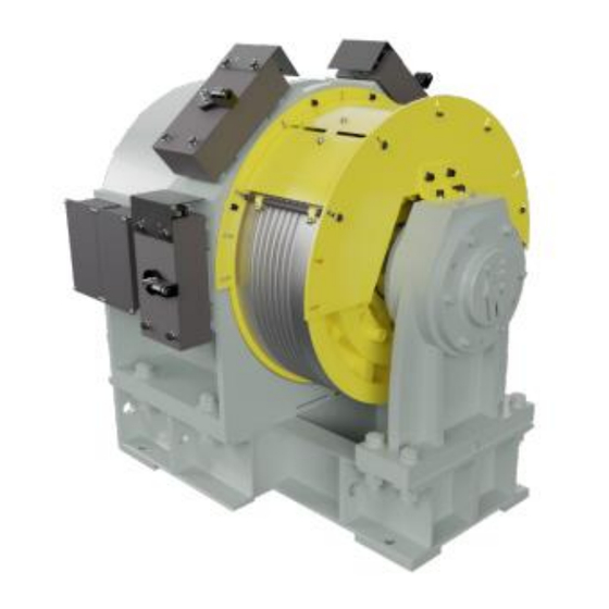
- Page 1 GLV-40S1 Gearless Machine Instruction Manual (#1196) © Hollister-Whitney Elevator Co. LLC #1Hollister-Whitney Parkway Quincy, IL 62305 Phone 217.222.0466 • Fax 217.222.0493 4/1/2022...
- Page 2 ASME A17.1; and all governing local codes. Every attempt has been made to ensure that this guide is accurate and up to date. Hollister-Whitney Elevator Co. LLC assumes no liability for consequences resulting from any error or omission. Please notify Hollister-Whitney Elevator Co.
-
Page 3: Table Of Contents
B U L L E T I N # 1 1 9 6 G L V - 4 0 S 1 G E A R L E S S T R A C T I O N M A C H I N E Contents Introduction ............. - Page 4 B U L L E T I N # 1 1 9 6 G L V - 4 0 S 1 G E A R L E S S T R A C T I O N M A C H I N E Brake Adjustment/Centering ..........
-
Page 5: Introduction
Section Introduction Description Thank you for choosing the Hollister-Whitney Elevator Corporation’s (HWEC), GLV-40S1 Gearless Machine! The GLV-40S1 machine has been designed for use in 1:1 roped machine room applications with VVVF controls. The machine is designed with 30 poles to provide smooth, quiet, and long-lasting operation. -
Page 6: Safety Precautions
Section Safety Precautions Read this section before any work is performed on elevator equipment. IMPORTANT – The procedures contained in this manual are intended for the use of qualified elevator personnel. In the interest of your personal safety and the safety of others, do NOT attempt ANY procedure that you are NOT qualified to perform. -
Page 7: Electrical Hazards
NOT touch exposed electrical connections or components while power is On. Product Specific Warnings WARNING GLV-40S1 series machines MUST be balanced during hoisting. See paragraph 3.4 for proper lifting configurations. WARNING Hang the elevator car before removing ANY bolts. Failure to do so may result in severe injury and equipment damage. -
Page 8: Arrival Of The Equipment
Section Arrival of the Equipment Receiving Immediately upon arrival of the machine, make a visual check for any external damage. If any damage incurred in transit is found, make notice of the claim in the presence of the carrier, and notify HWEC. -
Page 9: Hoisting
B U L L E T I N G L V - 4 0 S 1 # 1 1 9 6 G E A R L E S S T R A C T I O N M A C H I N E Hoisting The machine weighs about 4500 pounds (2040 kg). -
Page 10: Moisture, Condensation
B U L L E T I N G L V - 4 0 S 1 # 1 1 9 6 G E A R L E S S T R A C T I O N M A C H I N E Moisture, Condensation Before installing the machine, and before any voltage is applied, check the machine for condensation, or any evidence of moisture or water. -
Page 11: Application
Application Overview The GLV-40S1 series machine is a synchronous permanent magnet gearless machine designed for elevators. The machine has 30 poles to provide smooth, quiet, and long-lasting operation. Its configuration allows elevator capacity up to 4000 lbs. with 1:1 roping, single wrap arrangement at 50% counterbalance with up to a 22000 lb. -
Page 12: Codes And Standards
B U L L E T I N G L V - 4 0 S 1 # 1 1 9 6 G E A R L E S S T R A C T I O N M A C H I N E PM MOTOR HOUSING BRAKE... - Page 13 B U L L E T I N G L V - 4 0 S 1 # 1 1 9 6 G E A R L E S S T R A C T I O N M A C H I N E Table 1 Maximum Detailed Specifications Page 4-3 Rev.
-
Page 14: Brake Specification
• Four brakes are supplied standard from the factory. Two brakes are meant to serve as a primary machine brake and the other two brakes as a secondary emergency brake. ® Please contact Hollister-Whitney for details regarding using a Rope Gripper as the emergency brake with a GLV-40S1 machine. -
Page 15: Installation
Section Installation Machine Mounting Before hoisting the machine into place, verify all the hoisting equipment is rated for the 4500 pounds (2040 kg) weight of the machine. See Section 3.4 Provide a level, structurally supported (rated for the load on the machine) machine space with proper clearance around the machine for maintenance and adjustments. -
Page 16: Electrical Connection
B U L L E T I N G L V - 4 0 S 1 # 1 1 9 6 G E A R L E S S T R A C T I O N M A C H I N E Figure 6 Electrical Connection Use the project wiring diagrams (with the motor configuration information) to connect the motor... - Page 17 B U L L E T I N G L V - 4 0 S 1 # 1 1 9 6 G E A R L E S S T R A C T I O N M A C H I N E CONNECTIONS CONTROLLER CONNECTIONS...
-
Page 18: Brake Adjustment/Centering
B U L L E T I N G L V - 4 0 S 1 # 1 1 9 6 G E A R L E S S T R A C T I O N M A C H I N E Brake Wiring •... - Page 19 B U L L E T I N G L V - 4 0 S 1 # 1 1 9 6 G E A R L E S S T R A C T I O N M A C H I N E When the air gap of brake is more than 0.022”...
- Page 20 B U L L E T I N G L V - 4 0 S 1 # 1 1 9 6 G E A R L E S S T R A C T I O N M A C H I N E 3.
-
Page 21: Encoder Connection
B U L L E T I N G L V - 4 0 S 1 # 1 1 9 6 G E A R L E S S T R A C T I O N M A C H I N E Encoder Connection The machines are supplied with Heidenhain ECN1313 2048 encoder. -
Page 22: Manual Brake Release
B U L L E T I N G L V - 4 0 S 1 # 1 1 9 6 G E A R L E S S T R A C T I O N M A C H I N E Manual Brake Release The brakes can be manually released in the event of loss of power. -
Page 23: Maintenance
Section Maintenance WARNING Before performing any maintenance checks on equipment, take all the necessary safety precautions to immobilize the car and counterweight to prevent any unintended movement during the maintenance period that may result in injury or death! General To keep equipment functioning efficiently, good maintenance practices must be established, observed, and maintained. -
Page 24: Bearings
B U L L E T I N G L V - 4 0 S 1 # 1 1 9 6 G E A R L E S S T R A C T I O N M A C H I N E Bearings Bearings have been sized for the maximum speeds, loads and capacities found in this manual at 50% duty. -
Page 25: Brake Wear
B U L L E T I N G L V - 4 0 S 1 # 1 1 9 6 G E A R L E S S T R A C T I O N M A C H I N E Brake Wear WARNING If the brake pad wears too much, the brake will be disabled. -
Page 26: Other Items
B U L L E T I N G L V - 4 0 S 1 # 1 1 9 6 G E A R L E S S T R A C T I O N M A C H I N E Other Items The traction wheel, brake shoe, and brake wheel are usually the only components that will wear. -
Page 27: Replacement
Section Replacement WARNING Have only qualified personnel perform the replacement work. The person who performs the replacement work must make sure that the machine power is off, and that the elevator will not move unexpectedly. Encoder Replacement Required Tools & Materials: •... - Page 28 B U L L E T I N G L V - 4 0 S 1 # 1 1 9 6 G E A R L E S S T R A C T I O N M A C H I N E Encoder Removal The encoder can be removed from the front of the machine.
- Page 29 B U L L E T I N G L V - 4 0 S 1 # 1 1 9 6 G E A R L E S S T R A C T I O N M A C H I N E 3.
- Page 30 B U L L E T I N G L V - 4 0 S 1 # 1 1 9 6 G E A R L E S S T R A C T I O N M A C H I N E 7.
- Page 31 B U L L E T I N G L V - 4 0 S 1 # 1 1 9 6 G E A R L E S S T R A C T I O N M A C H I N E Encoder Installation What’s in the box.
- Page 32 B U L L E T I N G L V - 4 0 S 1 # 1 1 9 6 G E A R L E S S T R A C T I O N M A C H I N E 3.
-
Page 33: Brake Replacement
B U L L E T I N G L V - 4 0 S 1 # 1 1 9 6 G E A R L E S S T R A C T I O N M A C H I N E 6. - Page 34 B U L L E T I N G L V - 4 0 S 1 # 1 1 9 6 G E A R L E S S T R A C T I O N M A C H I N E Brake Removal 1.
- Page 35 B U L L E T I N G L V - 4 0 S 1 # 1 1 9 6 G E A R L E S S T R A C T I O N M A C H I N E 7.
-
Page 36: Support Documents
Section Support Documents Outline and Item Drawing See replaceable parts list and outline drawing next page. Page 8-1 Rev. A - 04/01/2022... - Page 37 B U L L E T I N G L V - 4 0 S 1 # 1 1 9 6 G E A R L E S S T R A C T I O N M A C H I N E Page 8-2 Rev.
- Page 38 B U L L E T I N G L V - 4 0 S 1 # 1 1 9 6 G E A R L E S S T R A C T I O N M A C H I N E Page 8-3 Rev.
- Page 39 B U L L E T I N G L V - 4 0 S 1 # 1 1 9 6 G E A R L E S S T R A C T I O N M A C H I N E Page 8-4 Rev.
-
Page 40: Notes
Section Notes Page 9-1 Rev. A - 04/01/2022... - Page 41 Product Information ECN 1313 ECN 1325 ERN 1387 Rotary Encoders with Plane-Surface Coupling for Elevator Servo Drive Control July 2017...
- Page 42 ECN/ERN 1300 series Rotary encoders with integral bearings for elevator technology • Simple installation • Rigid shaft coupling • Plane-surface coupling for large mounting tolerances • Uniform dimensions for various electrical interfaces = Bearing of mating shaft = Bearing of encoder ...
- Page 43 Absolute Incremental ECN 1325 ECN 1313 ERN 1387 Part number 683643-xx 768295-xx 749146-xx Interface EnDat 2.2 1 V Ordering designation EnDat22 EnDat01 – Position values/revolution 33 554 432 (25 bits) 8192 (13 bits) Z1 track Electrically permissible 15 000 rpm ...
- Page 44 Electrical connection Pin layouts ECN 1313 pin layout 17-pin coupling or 12-pin PCB connector fl ange socket M23 Power supply Incremental signals Serial data transfer Sensor Sensor Internal A– B– DATA DATA CLOCK CLOCK shield Brown/ Blue White/ White Green/ Yellow/ Blue/ Red/...
- Page 45 ERN 1387 pin layout 17-pin coupling or 14-pin PCB connector fl ange socket M23 Voltage supply Incremental signals Sensor Sensor Internal A– B– R– shield Brown/ Blue White/ White Green/ Yellow/ Blue/Black Red/Black Black Green Green Black Black Other signals C–...
- Page 46 THIS DRAWING IS SUPPLIED AS A REPRESENTATION OF THE EQUIPMENT DRAWN SCALE MATERIAL THIRD ANGLE PROJECTION REFERENCE TOL. HOLLISTER-WHITNEY ELEVATOR CO. LLC ("MANUFACTURER") HAS AGREED TO AS PURCHASED, SEE SUPPLY. SLIGHT ADJUSTMENTS MAY OCCUR DURING MANUFACTURING AND ALL DIMENSIONS REFERENCE INSTALLATION. ANY MODIFICATIONS NOT APPROVED IN WRITING BY...
- Page 47 CABLE LENGTH UP TO 30 M BLUE YELLOW GREEN VIOLET (CLOCK -) BLACK (CLOCK +) BLUE WHITE YELLOW (CLOCK-) VIOLET GRAY GREEN (CLOCK+) BLACK BROWN PINK WHITE BROWN PINK GRAY...
- Page 48 CABLE LENGTH OVER 40 METERS VIOLET BLUE BROWN (0.25mm wire) GREEN BLACK BLUE WHITE VIOLET BROWN (0.25mm wire) GREY GREEN BLACK BROWN (1.0mm wire) PINK WHITE PINK BROWN (1.0mm wire) GREY...
- Page 49 Hollister-Whitney Elevator Corporation #1 Hollister-Whitney Parkway Fax: 217-222-0493 Quincy, IL 62305 e-mail: info@hollisterwhitney.com Phone: 217-222-0466 www.hollisterwhitney.com GERMAN ENGLISH -------------------------------------------------------------- BLAU ---------------------------------------------------------- BLUE GELB ----------------------------------------------------- YELLOW GRÜN ------------------------------------------------------- GREEN VIOLETT -------------------------------------------------- VIOLET SCHWARZ ------------------------------------------------- BLACK BRAUN ---------------------------------------------------- BROWN WEIβ --------------------------------------------------------- WHITE...
Need help?
Do you have a question about the GLV-40S1 Series and is the answer not in the manual?
Questions and answers