Table of Contents
Advertisement
Hollister-Whitney Elevator Co., LLC
2603 North 24th Street
Fax: 217-222-0493
Quincy, IL 62305
e-mail: info@hollisterwhitney.com
Phone: 217-222-0466
www.hollisterwhitney.com
INSTALLATION, MAINTENANCE, AND
TROUBLE SHOOTING INSTRUCTIONS
FOR
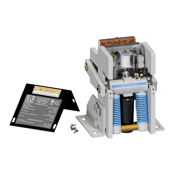
Models #620, #621, #622, #624, #625, #626, & #626SPL
Hollister-Whitney "Rope Gripper
" & Pumping Unit
®
(Patent # 5,228,540)
CSA Certification File #88181
BULLETIN 1144
Page 1 of 29
11/12/19
Advertisement
Table of Contents


Need help?
Do you have a question about the Rope Gripper 620 and is the answer not in the manual?
Questions and answers