Renesas RX700 Series User Manual
Envision kit
Hide thumbs
Also See for RX700 Series:
- User manual (60 pages) ,
- User manual (53 pages) ,
- Manual (66 pages)
Table of Contents
Advertisement
Quick Links
RX72N Group
32
32-Bit MCU
RX Family/RX700 Series
All information contained in these materials, including products and product specifications,
represents information on the product at the time of publication and is subject to change by
Renesas Electronics Corp. without notice. Please review the latest information published by
Renesas Electronics Corp. through various means, including the Renesas Electronics Corp.
website (http://www.renesas.com).
www.renesas.com
RX72N Envision Kit User's Manual
Rev.1.00 Mar. 2020
Advertisement
Table of Contents

Related Manuals for Renesas RX700 Series


Summary of Contents for Renesas RX700 Series
- Page 1 All information contained in these materials, including products and product specifications, represents information on the product at the time of publication and is subject to change by Renesas Electronics Corp. without notice. Please review the latest information published by Renesas Electronics Corp. through various means, including the Renesas Electronics Corp.
- Page 2 Renesas Electronics disclaims any and all liability for any damages or losses incurred by you or any third parties arising from the use of any Renesas Electronics product that is inconsistent with any Renesas Electronics data sheet, user’s manual or other Renesas Electronics document.
- Page 3 Unit Products The following usage notes are applicable to all Microprocessing unit and Microcontroller unit products from Renesas. For detailed usage notes on the products covered by this document, refer to the relevant sections of the document as well as any technical updates that have been issued for the products.
- Page 4 The following documents apply to the RX72N Envision Kit. Make sure to refer to the latest versions of these documents. The newest versions of the documents listed may be obtained from the Renesas Electronics website (www.renesas.com/envision2).
- Page 5 Pmod™ License Digilent Inc. Agreement page. QSPI Quad Serial Peripheral Interface QVGA Quarter Video Graphics Array Random Access Memory Renesas Flash Programmer RMII Reduced Media Independent Interface Read Only Memory SD Card Secure Digital Card SDHI Secure Digital Host Interface...
-
Page 6: Table Of Contents
Table of Contents 1. Overview .......................... 1 Package Contents ............................1 Purpose ..............................1 Features ..............................1 Preparation ..............................1 RX72N Envision Kit Specifications ......................2 Block Diagram ............................3 2. External View ........................4 3. Component Layout Diagram .................... 6 4. - Page 7 7. Developing Code ......................25 Using e studio ............................25 Using CS+ ..............................26 8. Additional Information ....................27...
-
Page 8: Overview
1. Overview Package Contents Thank you for purchasing the RX72N Envision Kit evaluation tool from Renesas (the product). The contents of the product package are as follows: RX72N Envision Kit (RTK5RX72N0C00000BJ) Note: USB cable not included. Purpose The product is an evaluation tool for Renesas MCUs. This manual describes the technical elements of the product’s hardware. -
Page 9: Rx72N Envision Kit Specifications
RX72N Envision Kit User's Manual 1. Overview RX72N Envision Kit Specifications Table 1-1 lists the specifications of the product. Table 1-1. RX72N Envision Kit Specifications Item Specification Evaluation MCU Model number: R5F572NNHDFB Package: 144-pin LQFP On-chip memory: ROM 4 MB + 64 KB, RAM 1 MB Board size Dimensions: 130.0 mm ×... -
Page 10: Block Diagram
RX72N Envision Kit User's Manual 1. Overview Block Diagram Figure 1-1 is a block diagram of the product. Figure 1-1. Block Diagram R20UT4788EJ0100 Rev.1.00 Page 3 of 27 Mar.27.20... -
Page 11: External View
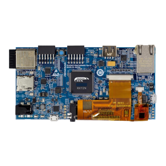
RX72N Envision Kit User's Manual 2. External View 2. External View Figure 2-1 is an external view of the LCD side of the product, Figure 2-2 is an external view of the component side (as shipped from the factory), and Figure 2-3 is an external view of the component side (without LCD). Figure 2-1. - Page 12 RX72N Envision Kit User's Manual 2. External View Figure 2-3. External View of Component Side (without LCD) R20UT4788EJ0100 Rev.1.00 Page 5 of 27 Mar.27.20...
-
Page 13: Component Layout Diagram
RX72N Envision Kit User's Manual 3. Component Layout Diagram 3. Component Layout Diagram Figure 3-1 is a component layout diagram of the product. Figure 3-1. Component Layout Diagram R20UT4788EJ0100 Rev.1.00 Page 6 of 27 Mar.27.20... -
Page 14: Operating Environment
Figure 4-1 shows the operating environment of the product. Install the integrated development environment (IDE), available on the following webpage, on the host PC. The necessary drivers will be installed as part of the IDE install process. https://www.renesas.com/development-tools USB cable RX72N Envision Kit Host PC Figure 4-1. -
Page 15: User Circuits
RX72N Envision Kit User's Manual 5. User Circuits 5. User Circuits Power Supply Circuit The board operates on 5 V of power supplied via USB Micro-B connector ECN1 or DC jack CN7. Figure 5-1 is a power supply system diagram. Figure 5-1. -
Page 16: Power Supply
The MCU, Ethernet PHY, Wi-Fi/BLE module, etc., on the board operate on 3.3 V. A 3.3 V power supply is generated from the 5 V power supply by the ISL80030 on-chip regulator with FET. Refer to the www.renesas.com website for details of the ISL80030. Figure 5-3 shows the 3.3 V power supply circuit. -
Page 17: Reset Circuit
The board is provided with an emulator. The emulator connector (ECN1) has a USB Micro-B configuration, and it serves as an interface for the integrated development environment (IDE) and Renesas Flash Programmer (RFP). Use a USB cable to connect the board to your PC. When the host PC is powered on, power is supplied to the board via the USB cable connection. -
Page 18: Dip Switches
RX72N Envision Kit User's Manual 5. User Circuits DIP Switches DIP switches SW1 and SW3 on the board are used to make a variety of settings. Figure 5-5 shows the locations of the DIP switches, and Table 5-1 and Table 5-2 list the settings of each switch. Figure 5-5. -
Page 19: Usb Serial Interface
PC. Figure 5-7. USB Serial Driver Install Messages If you do not have a copy of the driver installer, you can download it from the following webpage: https://www.renesas.com/us/en/software/D6000699.html R20UT4788EJ0100 Rev.1.00 Page 12 of 27... -
Page 20: Pmod™ Connectors
RX72N Envision Kit User's Manual 5. User Circuits Pmod™ Connectors Connectors CN5 and CN6 are compliant with Pmod Interface Type 2A and provide connections to the evaluation MCU. Be careful not to bend or damage the pins when installing a Pmod™ module. The Pmod™ module is susceptible to damage from electrostatic discharge (ESD). -
Page 21: User Switch
RX72N Envision Kit User's Manual 5. User Circuits User Switch The board is provided with a user switch (SW2) that you can utilize as you like. The user switch is connected to the P107/IRQ15 port of the 144-pin evaluation MCU. Figure 5-9. -
Page 22: Ethernet Interface
RX72N Envision Kit User's Manual 5. User Circuits 5.11 Ethernet Interface The board is provided with an Ethernet controller, which is connected to the MCU’s Ethernet module. The MCU supports full-duplex and half-duplex modes and transfer rates of 10 Mbps and 100 Mbps. Table 5-7 lists information related to Ethernet connections. -
Page 23: Microsd Slot
RX72N Envision Kit User's Manual 5. User Circuits 5.12 microSD Slot The microSD slot is connected to the MCU via the SDHI interface. The data bus width is wide bus (4-bit), and compatible devices are SD memory cards (SD, SDHI, and SDXC) and SDIO cards. Figure 5-10. -
Page 24: Usb Host Interface
RX72N Envision Kit User's Manual 5. User Circuits 5.13 USB Host Interface The USB Host interface connects the evaluation MCU and the USB Host connector (type A). USB connections to devices compatible with version 2.0 are supported. The supported transfer rates are full speed (12 Mbps) and low speed (1.5 Mbps). -
Page 25: Serial Flash
RX72N Envision Kit User's Manual 5. User Circuits 5.14 Serial Flash The board is mounted with a MX25L3233F (32 Mbit) serial flash memory chip from MACRONIX. It is connected to the MCU via the QSPI interface. It supports the MCU’s SPI operation modes 0 and 3. Figure 5-12. -
Page 26: D2Audio Processor And Amplifier For Active Speaker
DAE-4 Development Tools The development tools are available for download on the following webpage. Renesas would collect my Renesas accounts for rights protection to manage who download the tool. Please note that anyone needs to accept above to download. https://www.renesas.com/products/audio-video/audio/digital-sound-processors.html#documents 5.15.5... - Page 27 RX72N Envision Kit User's Manual 5. User Circuits Table 5-12. Dongle Tool Connection Correspondences Dongle (Female Socket) EVB (IC Clip) EEWP (12) WP (T4) SCL (3) SCL (T5) SDA (4) SDA (T6) BOOT_EE/I C (11) IRQA (T7) EEWP (7) RES (T8) +5V (13) 5V (T9) GND (14)
-
Page 28: Mems Microphones
RX72N Envision Kit User's Manual 5. User Circuits 5.16 MEMS Microphones The microphones used are the ICS-43434 from TDK, and they are connected to the evaluation MCU via the S interface. Since the microphones for sound input are on the component side, sound is input from the panel side. -
Page 29: Light Sensor
RX72N Envision Kit User's Manual 5. User Circuits 5.17 Light Sensor The ISL29034 is used as the light sensor, and it is connected to the evaluation MCU via the I C interface. Figure 5-15. Light Sensor Connection Diagram Table 5-14. Light Sensor Pin Assignments Signal Function/Application RX72N... -
Page 30: Leds
RX72N Envision Kit User's Manual 5. User Circuits 5.18 LEDs There are five LEDs mounted on the board. Table 5-15 lists the colors and functions of the LEDs. Table 5-15. LED Connection States Color Function RX72N Port LED1 Green 3.3 V power LED on: 3.3 V power supply status Green On-board debugger status LED2... -
Page 31: Usage Precautions
RX72N Envision Kit User's Manual 6. Usage Precautions 6. Usage Precautions Additional Load When adding additional load while using the USB connection to supply power to the board, be aware that the maximum capacity when operating at 3.3 V is 300 mA. When adding additional load while using an external power supply, the maximum capacity is 500 mA regardless of the operating voltage. -
Page 32: Developing Code
RX72N Envision Kit User's Manual 7. Developing Code 7. Developing Code Using e studio Figure 7-1 shows the settings to use in e studio when creating a new project for use with the RX72N Envision Kit. • Debug hardware: Select E2 Lite (RX). •... -
Page 33: Using Cs
RX72N Envision Kit User's Manual 7. Developing Code Using CS+ Figure 7-2 and Figure 7-3 show the settings to use in CS+ when creating a new project for use with the RX72N Envision Kit. Debug tool used: Select Debug → Debug Tool Used → RX E2 Lite. •... -
Page 34: Additional Information
The contents of this document are subject to change in whole or in part without prior notice. This document is copyright of Renesas Electronics Corporation. The contents of this document may not be copied in whole or in part without the prior written approval of Renesas Electronics Corporation. - Page 35 RX72N Envision Kit User’s Manual Revision History Rev. Date Description Page Summary ⎯ 1.00 Mar.27.20 First Edition issued...
- Page 36 RX72N Envision Kit User’s Manual Publication Date: Rev.1.00 Mar.27.20 Published by: Renesas Electronics Corporation...
- Page 37 RX72N Group R20UT4788EJ0100...
Need help?
Do you have a question about the RX700 Series and is the answer not in the manual?
Questions and answers