Table of Contents
Advertisement
Quick Links
OPERATOR'S MANUAL
INCLUDING: OPERATION, INSTALLATION & MAINTENANCE
READ THIS MANUAL CAREFULLY BEFORE INSTALLING,
It is the responsibility of the employer to place this information in the hands of the operator. Keep for future reference.
SERVICE KITS
637419 for air section repair (see page 5).
637420 for fluid section repair (see page 3).
PUMP DATA
Models . . . . . . . . . . . . . . . . . . . . . . . . . . . . . . . . . . . . . . 670021
Pump Type . . . . . . . . . . . . . Metallic Air Operated Double Diaphragm
Wetted End Material. . . . . . . . . . . . . . . . . . . . . . . . . Aluminum
Weight . . . . . . . . . . . . . . . . . . . . . . . . . . . . . . . . 19 lbs (8.62 kgs)
Maximum Air Inlet Pressure . . . . . . . . . . . 120 psig (8.3 bar)
Maximum Material Inlet Pressure . . . . . . 10 psig (0.69 bar)
Maximum Outlet Pressure . . . . . . . . . . . . . 120 psig (8.3 bar)
Maximum Flow Rate (flooded inlet) . . . 35 gpm (133 lpm)
Maximum Particle Size . . . . . . . . . . . . . . . . 1/8" dia. (3.2 mm)
Maximum Temperature Limits (diaphragm / ball / seal / seat
material)
Hytrel® . . . . . . . . . . . . . . . . . . . . . . . . . -20° to 150° F (-29° to 66° C)
Polypropylene. . . . . . . . . . . . . . . . . . 35° to 175° F (2° to 79° C)
Polyurethane . . . . . . . . . . . . . . . . . . . 10° to 150° F (-12° to 66° C)
Dimensional Data . . . . . . . . . . . . . see page 7
Noise Level @ 70 psig, 60 cpm . . . . . . . . . . 64.5 db(A)
The pump sound pressure levels published here have been updated
to an Equivalent Continuous Sound Level (LA
ANSI S1.13-1971, CAGI-PNEUROP S5.1 using four microphone locations.
GENERAL DESCRIPTION
The ARO diaphragm pump offers high volume delivery even at low
air pressure and a broad range of material compatibility options
are available. Refer to the model and option chart. ARO pumps
feature stall resistant design, modular air motor / fluid sections.
Air operated double diaphragm pumps utilize a pressure differen-
tial in the air chambers to alternately create suction and a positive
fluid pressure in the fluid chambers, valve checks insure a positive
flow of fluid.
Pump cycling will begin as air pressure is applied and will continue
to pump and keep up with the demand. It will build and maintain
line pressure and will stop cycling once maximum line pressure is
reached (dispensing device closed) and will resume pumping as
needed.
INGERSOLL RAND COMPANY LTD
209 NORTH MAIN STREET - BRYAN, OHIO 43506
(800) 495-0276
FAX (800) 892-6276
arozone.com
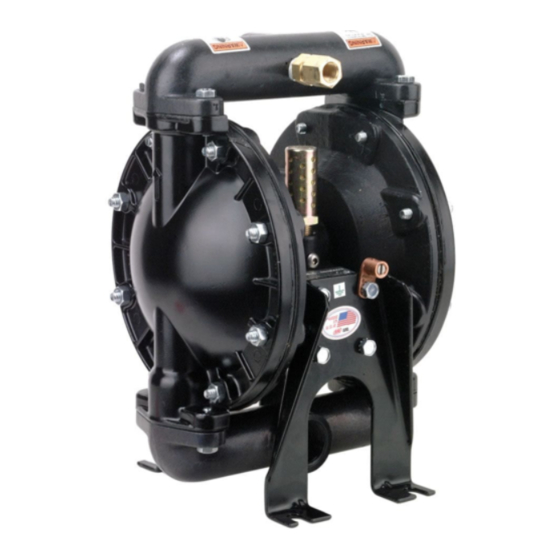
1" DIAPHRAGM PUMP
1:1 RATIO (METALLIC)
OPERATING OR SERVICING THIS EQUIPMENT.
) to meet the intent of
eq
© 2016
CCN 15206428
670021
RELEASED:
REVISED:
(REV: G)
Figure 1
11-21-03
10-28-16
Advertisement
Table of Contents

Subscribe to Our Youtube Channel
Related Manuals for Ingersoll-Rand 670021


Summary of Contents for Ingersoll-Rand 670021
- Page 1 Models ........670021...
-
Page 2: Operating And Safety Precautions
Do not attempt to return a pump to the factory or service center that contains hazardous material. Safe handling practices must comply with local and national laws and safety code requirements. Page 2 of 8 670021 (en) -
Page 3: Air And Lube Requirements
Service kits are divided to service two separate diaphragm pump functions: 1. AIR SECTION, 2. FLUID SECTION. The Fluid Section is divided further to match typical part Material Op- tions. PARTS LIST / 670021 FLUID SECTION FLUID SECTION PARTS Item Description (size) Qty Part No. -
Page 4: Torque Requirements
PARTS LIST / 670021 FLUID SECTION COLOR CODE DIAPHRAGM BALL MATERIAL COLOR COLOR HYTREL Cream N / A URETHANE N / A For the air motor section, see pages 5 & 6 26� 2� 1� 3� Inlet 3� 14 �... -
Page 5: Air Motor Parts
Install one of the (121) sleeve bushings, (119) “O” rings, (120) spacers and the remaining (121) bushing. Carefully push (118) pilot rod into bushings etc. and retain on each end with the two (122) “O” rings. Retain with (123) screws. Replace (104) retaining rings. 670021 (en) Page 5 of 8... -
Page 6: Pilot Valve
PARTS LIST / 670021 AIR MOTOR SECTION IMPORTANT BE CERTAIN TO ORIENT (115) SPACER LEGS AWAY FROM BLOCKING INTERNAL PORTS WHEN REASSEMBLING AIR SECTION. �114 �113 MAJOR VALVE See cross section detail Figure 4. Figure 3 �128 �195 �123 195�... -
Page 7: Troubleshooting
11-9/16” (293.7 mm) 6-1/2” 12-1/2” (165.1 mm) (317.5 mm) Inlet 1-1/4” (31.8 mm) 6-1/4” 13/32” Slot (158.8 mm) (10.3 mm) 1 - 11 BS Rp 4” 7-5/16” (101.6 mm) ( 185.8 mm) Figure 5 670021 (en) Page 7 of 8... - Page 8 PN 97999-1070 Page 8 of 8 670021 (en)
Need help?
Do you have a question about the 670021 and is the answer not in the manual?
Questions and answers