
Related Manuals for Lacanche FCE Range


Summary of Contents for Lacanche FCE Range
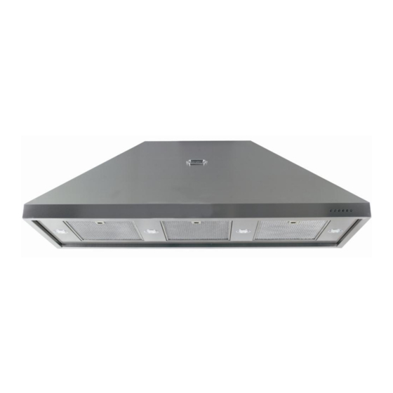
- Page 1 Use and maintenance instructions for FCE Range High Performance extraction systems...
-
Page 2: Table Of Contents
INDEX PAGE SECTION 1 CHECKLIST OF ITEMS SECTION 2 EXTRACTION PERFORMANCE SEECTION 3 IMPORTANT INFORMATION SECTION 4 INSTALLATION SECTION 5. ELECTRICAL INSTALLATION SECTION 6. OPERATING INSTRUCTIONS SECTION 7. MANTENANCE 11-12 SECTION 8. TECHNICAL SPECIFICATIONS... -
Page 3: Section 1 Checklist Of Items
SECTION 1. CHECKLIST OF ITEMS Check that the following items have been supplied: 1 extractor hood (Complete with blower motor, lighting, mains supply cord and grease filter(s) SECTION 2. EXTRACTION PERFORMANCE The most important influence on the performance of the extractor is the design of the ducting which takes the exhaust air from the extractor to the outside. - Page 4 SECTION 3. IMPORTANT INFORMATION The following minimum headroom is required to accommodate the cooker and hood: Cooker height (nominal): 900mm Min Cooker-to-hood clearance 800mm Clearance with FdeF backsplash 850mm Hood height: 450mm Advice only: Clearance between hood and ceiling: (recomme nded) Required ceiling height (min):...
-
Page 5: Section 4 Installation
SECTION 4. INSTALLATION Removing the Grease Filter(s) Place extractor on its backplate on a horizontal surface. The grease filter(s) have an integrated sprung latch and release mechanism. Release the latch by pulling the lever and remove the filter. The filter is replaced by locating the fixed tabs on the filter into corresponding 2mm slots in the baseplate and then pushing the filter into position with the latch held open. - Page 6 With the motor(s) disconnected remove the three fixing screws holding the motor plate to the back panel of the hood. See Fig 2 Fixing screws motor plate rear of the hood Fig 2 With the motor(s) disconnected remove the three fixing screws holding the motor plate to the top panel of the hood.
- Page 7 With all the fixings screws and the motors disconnected remove the motor plate from the hood and reverse the position of the motor(s). See Fig 4 Fig 4 Duct Installation Make a hole or holes in the walls and/or ceiling, as necessary, in order to take 150mm diameter ducting from the extractor spigot(s) to the outside.
- Page 8 FCE1000...
- Page 9 Fixings must be used which are suitable for the type of wall construction. Your Lacanche hood has four fixing holes and two suspending Brackets. Offer the hood into position and insure that the hood is level. Mark the fixing holes and suspending brackets.
- Page 10 Fig 7 Connecting Ducting spigot to hood...
-
Page 11: Section 5. Electrical Installation
Section 5. Electrical Installation ELECTRICAL HAZARD DISCONNECT ELECTRICAL SUPPLY BEFORE PROCEEDING FURTHER The extractor is a stationary appliance designed to be connected by fixed wiring to the electrical supply. A competent electrical technician must perform the electrical installation. The hood must be fed from a 230Vac single phase electrical supply using a switched spur fitted with a 3A fuse for single blower models or a 5A fuse for double blower models . -
Page 12: Section 6. Operating Instructions
Section 6. Operating Instructions Switch power on at the fused spur. The extractor has 5 push-buttons which illuminate when selected TL to switch on/off lights T1 to switch on motor at the first speed T2 second speed ... -
Page 13: Section 7. Mantenance
Section 7. Maintenance WARNING Unplug the appliance or switch off the circuit breaker before carrying out maintenance operations. Regular maintenance is essential to ensure good performance and long-life. To clean the stainless steel surfaces of the hood use a damp cloth only. Do not use abrasive cleaning materials or products on any surface. - Page 14 LIGHTING Using a small flat blade screw driver remove the lens cover replace thE LED with one that has the same features (1.2W) Do not use a higher rated lamp as this can cause damage to the electrical system that will not be covered under warranty ...
-
Page 15: Section 8. Technical Specifications
SECTION 8. Technical Specifications CONSTRUCTION CHARACTERISTICS • STAINLESS STEEL SHEET BODY Thickness 8/10 • TELESCOPIC STACK IN VARIOUS DIMENSIONS • ALUMINIUM BODY AISI 304 - 430. GENERAL CHARACTERISTICS • ELECTRICAL SYSTEM ACCORDING TO THE INTERNATIONAL REGULATIONS • 2 x 1.2W LED LIGHTS •...
Need help?
Do you have a question about the FCE Range and is the answer not in the manual?
Questions and answers