Table of Contents

Summary of Contents for Lacanche BFUS900
- Page 1 Use and maintenance instructions for BFUS900 High Performance Built-in extraction systems FOURNEAUX DE FRANCE LTD 3 ALBION CLOSE, NEWTOWN BUSINESS PARK, POOLE, DORSET BH12 3LL TEL:01202 733011 FAX:01202 733499 INFO@FDEF.CO.UK WWW.FDEF.CO.UK...
-
Page 2: Table Of Contents
INDEX SECTION 1. CHECKLIST OF ITEMS Page SECTION 2. EXTRACTION PERFORMANCE Page SECTION 3. IMPORTANT INFORMATION Page SECTION 4. INSTALLATION Page SECTION 5. REMOVING AND REFITING THE GREASE FILTERS Page SECTION 6. ELECTRICAL INSTALLATION Page SECTION 7. WARNING Page SECTION 8. OPERATING INSTRUCTIONS Page SECTION 9. -
Page 3: Section 1. Checklist Of Items
If installing the BFUS900 extractor into a chimney it is recommended that the chimney must be lined and that the diameter of the chimney must be a minimum of 150mm. Consideration must be give to the length of the chimney, a long chimney will reduce the performance of the extractor. -
Page 4: Section 4. Installation
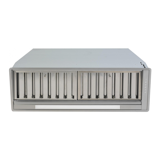
Your Lacanche BFUS900 extraction hood is designed to be fitted into kitchen furniture, over mantles, or a chimney and is vented from the top. When installing the extractor care should be taken on the position that the extractor is installed. The extractor should be installed as far forward as possible over the Lacanche range. - Page 5 Duct Installation Make a hole or holes in the walls and/or ceiling, as necessary, in order to take 150mm diameter ducting from the extractor spigot(s) to the outside. The exhaust duct route length should be kept as short as possible with as few bends as possible. ...
- Page 6 Fig 4 Remove grease filters Fig 5 Adjust lateral springs Fig 6 Warning Do not reduce the ducting diameter from 150mm as this will affect the performance of the hood and could damage the motor. Damage caused to the hood by incorrect ducting will not be covered by warranty.
-
Page 7: Section 5 Removing And Refiting The Grease Filters
Section 5 REMOVING AND REFITING THE GREASE FILTERS Side the filter towards the back of the extractor as per Fig 8 Pull the filter downwards away from the extractor To refit the grease filter position the rear of the filter into the grease tray as per Fig.9 then push the filter upwards until it locks into position Fig 8 Removing the Grease Filter Fig 9 Refitting the Grease Filter... -
Page 8: Section 6. Electrical Installation
SECTION 6. ELECTRICAL INSTALLATION ELECTRICAL HAZARD DISCONNECT ELECTRICAL SUPPLY BEFORE PROCEEDING FURTHER The extractor is a stationary appliance designed to be connected by fixed wiring to the electrical supply. A competent electrical technician must perform the electrical installation. The hood must be fed from a 230Vac single phase electrical supply using a switched spur fitted with a 3A fuse for single ... -
Page 9: Section 9. Maintenance
After 30 hours of use the push buttons on the control panel will flash and signal saturation of the grease filters. To reset the alarm press button F. Please see section 9 for instruction on cleaning the grease filters SECTION 9. - Page 10 Replacing the Halogen lamps To replace the halogen lamp using a small flat blade screw driver gently easy the lamp away from the extractor as per Fig.14 Replace the bulb with the same rated type bulb 20w 12 volt halogen Fig 14 Replacing Halogen Lamp...
- Page 11 SECTION 10. CONSTRUCTION AND TECHNICAL SPECIFICATIONS 4.1 CONSTRUCTION CHARACTERISTICS STAINLESS STEEL SHEET BODY Thickness 8/10 ALUMINIUM BODY AISI - 430. 4.2 GENERAL CHARACTERISTICS ELECTRICAL SYSTEM ACCORDING TO THE INTERNATIONAL REGULATIONS 4 x 20W HALOGEN LIGHTING 4 OPERATING SPEEDS COOKING COUNTER LIGHTING SYSTEM 4.3 TECHNICAL DATA FLOW RATE PER HOUR MC 1000 STATIC PRESSURE 400 Pa...


Need help?
Do you have a question about the BFUS900 and is the answer not in the manual?
Questions and answers