
Subscribe to Our Youtube Channel
Related Manuals for RLE Technologies SeaHawk 10K

Summary of Contents for RLE Technologies SeaHawk 10K
- Page 1 User Guide User Guide Version 05.22 Documented Using Firmware Version 3.2 www.rletech.com RLE Technologies 800.518.1519...
- Page 2 Revision History Rev. No. Date Rev. No. Date April 2011 December 2016 May 2011 05.22 May 2022 August 2011 December 2011 November 2012 August 2013 August 2013 September 2013 2.5.a July 2014 September 2015 SeaHawk 10K User Guide 800.518.1519...
- Page 3 A request for assistance may be sent to support@rletech.com. Otherwise, please call us directly at: 800.518.1519. The following information is located on the bottom of each SeaHawk 10K unit. Please have this information available whenever a technical support call is placed:...
- Page 4 SeaHawk 10K User Guide...
-
Page 5: Table Of Contents
Packet Communications for the SeaHawk 10K ........ - Page 6 Configure the SeaHawk 10K for Modbus Communications ......43 SeaHawk10K User Guide...
- Page 7 Figure 2.1 SeaHawk 10K Physical Inputs........
- Page 8 SeaHawk 10K User Guide 800.518.1519...
- Page 9 Configuration Reference ..........41 rletech.com SeaHawk 10K User Guide...
- Page 10 SeaHawk 10K User Guide 800.518.1519...
-
Page 11: Product Overview
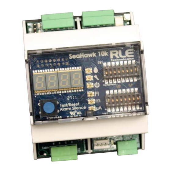
Capable of accommodating up to 10,000 feet (3048m) of sensing cable, the SeaHawk 10K has an audible alarm and can communicate via Modbus. As a stand-alone solution, the SeaHawk 10K provides alarm notification and numeric distances on its front panel. - Page 12 Product Overview User Configuration and Communication The SeaHawk 10K’s front panel display – which includes a four-digit LED panel and six LED indicators – provides information about its status, including the following: Leak detected Cable fault detected Power status Configured unit of measure Leak detection cable’s amperage value...
-
Page 13: Installation And Configuration
Electrostatic discharge (ESD) protection 2.2. Physical Connection Overview The SeaHawk 10K contains two circuit boards: The top circuit board houses operational controls and displays. SeaHawk 10K operational information is found in Chapter 3. The lower circuit board houses the connectors for: –... -
Page 14: Mount The Seahawk 10K
2.3. Mount the SeaHawk 10K The SeaHawk 10K can be mounted inside a panel or on a DIN rail. The device has two adjustable orange clips on the bottom. Push the clips out to expose two screw holes that allow the device to be mounted in a panel;... -
Page 15: Establish Physical Connections
BMS whenever a leak, cable fault, or cable contamination is detected. Insert the wires into the appropriate slots on TB1 to connect the relay output to the desired panel or controller. Figure 2.5 Relay Output Connection TB1 rletech.com SeaHawk 10K User Guide... -
Page 16: Tb2: Leader Cable
DIP Switch 5, SW1 - Latched or Unlatched Alarms 2.4.2 TB2: Leader Cable A 15-foot (4.57m) section of non-sensing leader cable is supplied with each SeaHawk 10K. The leader cable connects sensing cable to the SeaHawk 10K, since sensing cable cannot connect directly to the unit. -
Page 17: Tb3 And Tb4: Input Power And Eia-485 Communications Port
Do not connect 120/230 VAC to the unit, or damage will occur to the circuitry. ARNING Run an isolated power supply to the location of the SeaHawk 10K, or use a DIN rail mountable power supply and mount it next to the SeaHawk 10K. -
Page 18: Figure 2.11 Tb3 And Tb4 Power Supply And Communications Connections
Installation and Configuration If you are installing more than one SeaHawk 10K, use the appropriate pinouts of TB3 and TB4 to create a daisy-chained Modbus connection. A grounded shield contact is provided for connection to shielded cable. If the shield contact is used, verify the power connector is properly grounded and there is no voltage potential between units on the Modbus network. -
Page 19: Jmp - Termination Jumper
In a daisy chain. The SeaHawk 10K ships with the jumper in the non-terminated position - over the two pins closest to the device enclosure. If your SeaHawk 10K is the only device in the application, or if it’s not the last unit in the daisy chain, leave the jumper where it is. -
Page 20: Set The Re-Alarm Interval
2.5.2 Set the Re-Alarm Interval The SeaHawk 10K can be set to re-alarm – after a leak or cable fault has been detected, the alarm will be re-sent at a 4 hour interval until the alarm condition has been resolved. This re- alarm triggers both the audible alarm and the Modbus readout. -
Page 21: Secure Sensing Cable To The Floor
If the cable must be installed in front of an air conditioning unit, place the J-clips 3 feet (0.91m) apart. Figure 2.17 Secure the Cable rletech.com SeaHawk 10K User Guide... -
Page 22: Apply Power To The Seahawk 10K
ARNING Do not connect 120/230 VAC to the unit, or damage will occur to the circuitry. An isolated power supply was run and power was connected to the SeaHawk 10K in Section 2.4.3 on page Ensure all connections are correct and all screw terminals are secure. - Page 23 IMPORTANT To avoid inaccurate readings, do not grip the cable with your hand. Verify that the SeaHawk 10K reports the leaks within approximately two feet of their actual physical location. Remove all simulated leak sources and return the system to its normal operating state.
- Page 24 Installation and Configuration SeaHawk 10K User Guide 800.518.1519...
-
Page 25: Operation
3.1. Front Panel Controls and Display The front panel of the SeaHawk 10K contains a 4-character LED and series of colored LEDs that are used together to convey device status and information regarding detected leaks and cable faults. A blue button is used to cycle the 4-character LED, silence the audible alarm, and reset the alarm. -
Page 26: Table 3.1 Front Panel Controls And Displays
In an alarm condition, whether the audible alarm is sounding or not, press and hold this button for 3 seconds to clear the alarm. Table 3.1 Front Panel Controls and Displays SeaHawk 10K User Guide 800.518.1519... -
Page 27: Manage Alarms
If there is dirt, grit, or grime on the cable, clean the cable with isopropyl alcohol and a clean rag. If the cable is in a high traffic area, move it or install a cable protector over it. rletech.com SeaHawk 10K User Guide... - Page 28 Operation SeaHawk 10K User Guide 800.518.1519...
-
Page 29: Modbus Communication
4.1.1.2 Function Field The function field is one byte in length and tells the SeaHawk 10K which function to perform. Functions are 03 (Read 4xxxx output registers) and 04 (Read 3xxxx input registers) are supported by the SeaHawk 10K. -
Page 30: Data Field
4.1.1.5 5-1.2 Exception Responses If a Modbus master sends an invalid command to the SeaHawk 10K or attempts to read an invalid register, an exception response is generated. The response packet will have the high order bit of the function code set to one. The data field of the exception response contains the exception error code. -
Page 31: Packet Communications For The Seahawk 10K
Packet Communications for the SeaHawk 10K 4.2.1 Function 03: Read Output Registers To read the SeaHawk 10K parameter values, the master must send a Read Output Registers request packet. The Read Output Registers request packet specifies a start register and the number of registers to read. - Page 32 Description Units Range 40006 Reset Alarm Resets the 0 = Disabled (do not 0-65535 SeaHawk 10K after an reset alarm) alarm state. 1 = Enabled (reset Alternatively, press and alarm) hold the front panel’s Test/Reset button for 3 Default: 0 (Disabled) seconds.
-
Page 33: Function 04: Read Input Registers
Modbus Communication 4.2.2 Function 04: Read Input Registers To read the SeaHawk 10K input values, the master must send a Read Input Registers request packet. The Read Input Registers request packet specifies a start register and the number of registers to read. -
Page 34: Rtu Framing
1 = Contamination detected 1 = Summary alarm 04-15 Spare Table 4.6 Status Flags (Register 30001) 4.3. RTU Framing The example below shows a typical Query/Response from an SeaHawk 10K module. Register Register Register Slave Function Count Bytes Data Data... -
Page 35: Calibrate Cable Length Via Modbus
4.4. Calibrate Cable Length via Modbus The length of sensing cable connected to the SeaHawk 10K can be calibrated through a Modbus-enabled system. This helps fine-tune a distance-read leak detection system. If no alarms are present, follow these steps to calibrate and test the system: Set the SW1 DIP switches for the correct cable resistance per foot, as follows: Figure 4.1 DIP Switch Settings for Ohms/Foot... - Page 36 This milliohms per foot value is your end result, and the number you will write to Modbus register 40008. Record this value. Access your Modbus-enabled system. Write the milliohms per foot resistance value to the SeaHawk 10K’s Modbus register 40008. Example: Leg2 Resistance (Modbus register 30007)
- Page 37 AINTENANCE HAPTER Follow these steps monthly to test the SeaHawk 10K and ensure that the device is functioning properly. If your SeaHawk 10K is hooked into a BMS or NMS, notify monitoring personnel before you begin to test the system.
-
Page 38: Preventive Maintenance
Preventive Maintenance SeaHawk 10K User Guide 800.518.1519... -
Page 39: Troubleshooting
SeaHawk 10K. If no voltage is present at the terminal block, check the power supply and circuit breaker that power the SeaHawk 10K. If voltage is present but no LEDs are illuminated, go to step 2. Contact RLE Technologies for further troubleshooting and evaluation. - Page 40 (<105°F). Agitate the cable in the solution, rinse with clear lukewarm water and wipe dry with a clean towel. Connect the cable to the SeaHawk 10K and test it to make sure the contaminates have been removed before reinstalling the cable under the floor.
-
Page 41: Configuration Reference
DIP switches in blocks SW1 and SW2. The configuration of a stand-alone SeaHawk 10K can be performed using the DIP switches on the front panel. If the SeaHawk 10K will be connected to a Modbus-equipped monitoring system, some of the configuration can be performed using the registers. -
Page 42: Dip Sw1 Settings
Configuration Reference A.2. DIP SW1 Settings DIP switch 1 manipulates basic configuration settings on the SeaHawk 10K. Dip switch 3 in SW1 is unused and should remain in the OFF position. Figure A.2 SW1 Dip Switch Configuration Settings SeaHawk 10K User Guide... -
Page 43: Dip Sw2 Settings
SW1 to set the communication baud rate. Then, use the switches on DIP SW2 as follows for the communications you plan to employ. A.3.1 Configure the SeaHawk 10K for Modbus Communications The Modbus address should be a number between 1 and 254. Adjust the individual switches until their sum equals the Modbus address. - Page 44 Configuration Reference SeaHawk 10K User Guide 800.518.1519...
Need help?
Do you have a question about the SeaHawk 10K and is the answer not in the manual?
Questions and answers