
Subscribe to Our Youtube Channel
Related Manuals for Scotchman GAA-500-90 CNC DT20


Summary of Contents for Scotchman GAA-500-90 CNC DT20
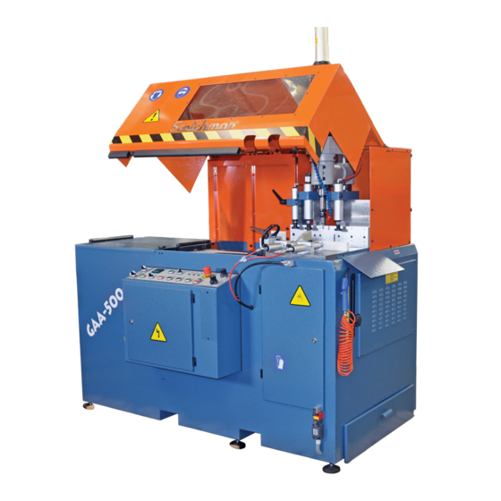
- Page 1 WWW.SCOTCHMAN.COM MODEL GAA-500-90 CNC DT20 AUTO UPCUT COLD SAW PRINTED OCTOBER 2020...
-
Page 2: Table Of Contents
TABLE OF CONTENTS 1.0 INTRODUCTION 1.1 Legislation applicable to the planning and construction of the machine. 1.2 Warranty 2.0 GENERAL MACHINE DATA 2.1 Machine identification data. 2.2 Technical data. 2.3 Electrical data. 2.4 Noise level. 3.0 INDICATIONS REGARDING TRANSPORT AND STORAGE 4.0 INSTRUCTIONS FOR ANCHORING AND SERVICE START-UP 4.1 Anchoring instructions. -
Page 3: Legislation Applicable To The Planning And Construction Of The Machine
2004/108/CEE On "Electromagnetic Compatibility". 1.2 WARRANTY Scotchman Industries, Inc. will, within 2 years of date of purchase, replace F.O.B. the factory or refund the purchase price for any goods which are defective in materials or workmanship and, at the seller’s option, returns the defective goods, freight and delivery prepaid, to the seller, which shall be the buyer’s sole and exclusive remedy for defective goods. -
Page 4: General Machine Data
2. GENERAL INFORMATION 2.1 MACHINE IDENTIFICATION DATA Model: GAA - 500 - 90° CNC DT20 Serial number: Manufacturing year: NOTE: In order to request spare parts, whether covered by the warranty or not, always indicate the model and serial number of the machine; as well as the name of the part and the code that appears in the last chapter of the parts exploded views. -
Page 5: Indications Regarding Transport And Storage
3. INDICATIONS REGARDING TRANSPORT/STORAGE The machine is delivered on a pallet in order to be transported by forklift. Store in the vertical position. Do not stack. If the machine remains stored for a long period of time, periodically lubricate it. Do not expose to the elements. -
Page 6: Instructions Regarding Blade Installation
4.3 BLADE INSTALLATION In order to install the blade, disconnect the power to the machine (deactivate the main switch) and press the EMERGENCY STOP BUTTON. Access the machine shaft through the sheet metal front, where the cutting oil sprayer is located. Lock the shaft, using the 12 ∅ rod that is provided with the tools, and loosen the blade nut. -
Page 7: Instructions For Use
5. INSTRUCTIONS FOR USE 5.1 PROPER AND IMPROPER USE This is an automatic cut-off machine, especially designed for cutting aluminum profiles. The use of the machine for cutting other materials is hereby prohibited. Such use may cause damage to the machine and put the health and safety of the worker at risk. - Page 8 Signal lamps: Red: emergency. Orange: Machine working in automatic cycle. Green: Power supplied to the machine. The machine is provided with one simple collet chucks with axial compensation for drill and tap. To change the collet chuck: Page 8...
-
Page 9: Manual Mode
5.3 MANUAL MODE With the operating mode switch in the MANUAL MODE, the operator can activate the hold down clamps, the feeder gripper and the saw blade. We recommend that very high feed rate for the saw blade or high feed rate on the shuttle feed not be used as this would greatly reduce the duration of the blade and the quality of the cut. - Page 10 TO CREATE, TO MODIFY AND TO EXECUTE A PROGRAM OF WORK: Select the program of work. Select the part list and the number of pieces. If you don’t program code of piece or number of pieces, the program is finished. Page 10...
- Page 11 To execute the program: A - To select line of beginning. B - To continue the program in the last line in execution. C - To execute the program from the first line. When the machine is prepared for the execution of the program, follow the steps below: Adjust the desired height of the cut, using the travel end stop at the right of the machine.
-
Page 12: General Rules And Safety Checks
5.5 GENERAL RULES AND SAFETY CHECKS Before using the machine, check the efficiency and perfect operation of all safety devices and check that the moving parts of the machine are not blocked, that there are no damaged parts and that all machine components are positioned and work correctly. - Page 13 ATTENTION: Every eighty hours LUBRICATE - 2 strokes - KLUBER ISOFLEX NBU 15. In the SETUP menu, we can modify the parameters of the machine. The password 7890 may be used by qualified personnel only. Page 13...
-
Page 14: Qualified Personnel For Maintenance And Repair Work
6.2 QUALIFIED PERSONNEL FOR MAINTENANCE/REPAIR All repairs shall be made exclusively by qualified personnel; thereby, always using original replacement parts. If not, the machine may be damaged or the user may be injured. The maintenance and cleaning of the machine must not be neglected. The life of the machine and its optimal operation depend on it considerably. -
Page 15: Manufacturer Recommendations
6.4 MANUFACTURER’S RECOMMENDATIONS In the event that the machine is broken down or the saw blades must be replaced, place a padlock on the protection switch and place the keys under the care of qualified personnel. Before working on any electrical devices, disconnect the plug from the power supply. If extension cords are used, ensure that the cable has the appropriate cross-section for the power of the machine. -
Page 16: Drawings And Schematics
7.0 DRAWINGS AND SCHEMATICS Page 16... - Page 17 Page 17...
- Page 18 Page 18...
- Page 19 Page 19...
- Page 20 Page 20...
- Page 21 Page 21...
-
Page 22: Main Frame Assembly
8.0 MAIN FRAME ASSEMBLY ITEM PART # DESCRIPTION 2059000064 Working plate 2050000322 Roker support 2050000322 Roker 2040000072 Rocker rotation shaft TD12500012 M-12 washer TD91212025 DIN 912 M-12 x 25 PIN 2059007522 7.5 HP III phase motor 2169000142 Motor pulley J16 TD93110050 DIN 931 M-10 x 50 PIN 2050000092... - Page 23 RIGHT SIDE CLAMP LEFT SIDE CLAMP Page 23...
-
Page 24: Shuttle Feed System
9.0 SHUTTLE FEED SYSTEM ITEM PART # DESCRIPTION Feeder Machine Support CTD93312040 DIN 933 M-12 x 40 Screw CTD93400010 M-10 Nut C2070000142 6204 2RS Bearing DIN 471 ∅ 20 Ring CTD47100120 Ball Screw ∅ 25 x 10 M200HBA2510 ∅ 25H6 x 925 Bar C2169011074 CTD79911040 DIN 7991 M-10 x 40 Screw... - Page 25 C20000A2510 25 x 10 Ball Screw Nut CTD91206020 DIN 912 M-6 x 20 Screw CTD79910835 DIN 7991 M-8 x 35 Screw End Of Travel Stop Cylinder Carriage Plane Nut M-10 CB0000P1070 M-10 x 70 Lever ∅ 40 x 10 D.E. Compact Cylinder CN0000C4010 CTD91206060 DIN 912 M-6 45 x 60 Screw...
-
Page 26: Optional Chip Collector - Wire Locations
BLUE Wire - goes to 0 Jumper Wire - goes to #2 Incoming Wires from Chip Collector DATE: SCALE: PART NAME: TOLERANCE (UNLESS SPECIFIED) Scotchman Inds. Scotchman Inds. Chip Collector 12/10/19 .0 = +/-.02 (.5mm) None .00 = +/-.01 (.25mm) GAA-500 &...
Need help?
Do you have a question about the GAA-500-90 CNC DT20 and is the answer not in the manual?
Questions and answers