
Subscribe to Our Youtube Channel
Related Manuals for Scotchman PRESSPRO 176MT


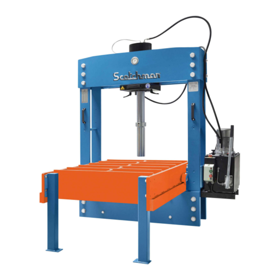
Summary of Contents for Scotchman PRESSPRO 176MT
- Page 1 PRESSPRO MODEL 176MT MOVABLE TABLE VERSION 2 - January 2022 SCOTCHMAN IND. - 180 E US HWY 14 - PO BOX 850 - PHILIP, SD 57567 Phone: 1-800-843-8844...
-
Page 2: Table Of Contents
5.2 De-aerating the hand pump .................14 5.3 Positioning of cylinder ..................14 PAGE 2 SCOTCHMAN INDS. - 180 E US HWY 14 - PO BOX 850 - PHILIP, SD 57567 Phone: 1-800-843-8844... - Page 3 Fig. 15 Adjusting press/cylinder position..............16 Fig. 16 Examples of type labels.................. .17 PAGE 3 SCOTCHMAN IND. - 180 E US HWY 14 - PO BOX 850 - PHILIP, SD 57567 Phone: 1-800-843-8844...
-
Page 4: Introduction
INTRODUCTION This manual helps you to install, operate and maintain your press. Always read this manual before you start working with the machine. If you have any questions, please contact your supplier. The manual gives safety instructions where necessary to assure a safe use of the machine. -
Page 5: General Information And Specifications
The given parameters of the piston movements are maximum values and can be up to 25% lower. Parameters are valid with minimum oil temperature of 86°F (30°C). PAGE 5 SCOTCHMAN IND. - 180 E US HWY 14 - PO BOX 850 - PHILIP, SD 57567 Phone: 1-800-843-8844... -
Page 6: Safety Advice
2. Safety advice Note: the supplier of the press can not be held responsible for any damages or injuries when the machine is modified or when maintenance is done by unqualified personnel. 2.1 Users responsibility Safe use of the hydraulic press can be achieved in daily work when all the necessary precautions are taken. -
Page 7: Out Of Use
· Any worn parts are visible. · The specifications of the power supply are not conform the information stated at the motor plate +/-10%. · The power supply plug is not equipped with a protection circuit. · Unprotected bystanders are present. www.scotchman.com PAGE 7... -
Page 8: Installation
(4) table-legs for this purpose . Fig. 2 Bolting Scotchman PressPro Model 176 MT to the floor. PAGE 8 SCOTCHMAN IND. - 180 E US HWY 14 - PO BOX 850 - PHILIP, SD 57567 Phone: 1-800-843-8844... -
Page 9: Installation Of The Hydraulic Unit
3.5 Installation of the hydraulic unit Hyd. Power Remove the back Unit is bolt & loosen the bolt shipped as on the angle iron. shown. Rotate the angle iron It must be to horizontal and bolted to the install the back bolt. angle iron Tighten both bolts. -
Page 10: Oil Tank Filling
On top of the cylinder there are (2) threaded holes. The centered hole is for the large diameter (18mm) hose from the reservoir. The other hole is for the small diameter (5mm) pressure gauge hose. Top of cylinder Fig. 6 Keep hoses straight - no sharp bends Make sure there are no sharp bends in the hoses between the clamps and connections to the hydraulic unit as shown above. -
Page 11: Electrical Connection
3.7 Electrical connection The machine must be connected to 220V 3ph or 440V 3ph power. The electric circuit must be protected by a fuse or circuit breaker with an adequate rating. The motor direction can be changed by swapping (2) of the incoming phases (SEE BELOW). NOTE: check if the turning direction of the motor is in the direction of the arrow, looking at the motor from above. -
Page 12: Hydraulic Unit
4.1 Hydraulic unit 4.1.1 On / Off switch The on / off switch is situated at the front of the hydraulic tank. · Pushing the green button will start the motor of the hydraulic unit. · Pushing the red button will stop the motor of the hydraulic unit immediately. -
Page 13: Pressure Gauge
The pressure gauge is located in the head (in front toward the top) of the press. The gauge shows the pressure in psi & bars. For this press the maximum pressure is as follows: PRESSURE PressPro 176MT: 3700psi (255 bar) GAUGE If this maximum pressure is reached, the maximum capacity of the press is reached as well. -
Page 14: Getting Started
5. Getting started To start the press for the first time, make sure: The press is installed correctly (see former paragraphs). The oil tank is filled with a sufficient amount of oil. The hydraulic hoses are tightened correctly to the cylinder and to the hydraulic unit. The machine is connected to the correct voltage &... -
Page 15: Regular Use
bow grip levers Fig. 14 Moving the cylinder Tip: working with the cylinder in the outer left or outer right position, will shorten the durability of the press. Working in the centre of the press is preferable. 5.4 Regular use Place the work piece on the table in alignment with the piston rod. -
Page 16: Working Period
5.5 Working period The machine is not designed for continuous operation. Maximum cycle intensity is 2 per minute. Maximum 10 minutes working time with maximum cycle intensity. Note: when you do not take the maximum working period into account, it can result in overheating the hydraulic oil and heating up the hydraulic unit. -
Page 17: Servicing And Maintenance
(front right side). When you have questions about the hydraulic unit, also mention its serial number. The label is located on the back of the hydraulic tank. SCOTCHMAN IND. HYDRAULIC PRESS MODEL PRESSPRO 176MT S/N 10061N120001 FRAME HYDRAULIC TANK Fig. 16 Examples of type labels... -
Page 18: Appendixes
7. Appendixes 7.1 Appendix I: Electric schematic for a press with a manual operated hydraulic unit EMERGENCY STOP LINE POWER NOTE: Swap (2) Incoming Power Wires to change Rotation 230V 460V 13 21 A1 Brown Brown Brown LC1DXX SCHNEIDER Black Black 14 22 Blue... - Page 19 SEE MOTOR TAG FOR DETAILS INCOMING SUPPLY (BY CUSTOMER) PROVIDE MAXIMUM UPSTREAM PROTECTION PER N.E.C. CODE 430-52 AND TABLE 430-152. E-STOP START PAGE 19...
- Page 20 PAGE 20...
-
Page 21: Appendix Iii: Spare Parts
7.3 Appendix III: Spare parts Parts list piston Description PressPro 176MT Piston shaft 160-506 O-ring 96x3 NBR 90 Piston 160-505 Valve set valve tip 30-200-515 valve housing 30-200-516 spring 30-200-D1970 bullet 30-200-ø12 U-seal 250-280-19 Ring 280-274-19.2 U-seal 265-280-12 PAGE 21... - Page 22 Parts list cylinder Description 160T Complete cylinder assy 160-500 Cylinder mounting strip 160-601 Handle assy 160-200-520 Piston head assy Piston head 160-507 Screw 30-200-M16x20 Wiper 125-140.2-10.1 Cylinder head 160-504 O-ring 260x5 NBR 70 U-seal 125-140-12.5 Complete piston assy 160-508 Bow grip assy Bow grip 60-200-06904- 1160081 Screw...
- Page 23 Parts list press SCOTCHMAN PRESSPRO MODEL 176MT MOVABLE TABLE Description PPTL-160 Pressure gauge assy Gauge 30-200-213,53-63 Screw M4x40 Hydraulic hose set 100-160-627 Complete hydraulic unit 160-200-3kW Rubber bumper Ø25-M6 Table support TL100-811 TL160-526 Shaft extension Bow grip assy Bow grip...
- Page 24 Parts list hydraulic unit PAGE 24...
- Page 25 Parts list hydraulic Unit Description Electric motor Tandempump Pressure relief Directional control valve Check valve Handpump Speed setting valve Pressure regulator (VABP) Knob pressure regulator Handle speed setting valve Filling plug Handle control valve Drain plug On- / Offswitch Emergency button Cabel / Plug Bell housing Pipes + couplings package...
Need help?
Do you have a question about the PRESSPRO 176MT and is the answer not in the manual?
Questions and answers