
Related Manuals for MSI E7505 Master-LS2


Summary of Contents for MSI E7505 Master-LS2
- Page 1 E7505 Master-LS2 MS-9121 (v1.X) E-ATX Mainboard Version 1.0 G52-S9121X1 This manual downloaded from http://www.manualowl.com...
-
Page 2: Fcc-A Radio Frequency Interference Statement
Manual Rev: 1.0 Release Date: Oct. 2002 FCC-A Radio Frequency Interference Statement This equipment has been tested and found to comply with the limits for a class A digital device, pursuant to part 15 of the FCC rules. These limits are designed to provide reasonable protection against harmful interference when the equip- ment is operated in a commercial environment. -
Page 3: Copyright Notice
Alternatively, please try the following help resources for further guidance. Visit the MSI website for FAQ, technical guide, BIOS updates, driver updates, and other information: http://www.msi.com.tw/ Contact our technical staff at: support@msi.com.tw... -
Page 4: Safety Instructions
Safety Instructions Always read the safety instructions carefully. Keep this User’s Manual for future reference. Keep this equipment away from humidity. Lay this equipment on a reliable flat surface before setting it up. The openings on the enclosure are for air convection hence protects the equipment from overheating. -
Page 5: Table Of Contents
Safety Instructions ..................iv Chapter 1. Getting Started ................ 1-1 Mainboard Specifications ..............1-2 Mainboard Layout ................1-5 MSI Special Features ................1-6 PC Alert™ III ................. 1-6 Live BIOS™/Live Driver™ ............1-6 Live Monitor™ ................1-8 Chapter 2. Hardware Setup ............... 2-1 Quick Components Guide .............. - Page 6 Audio Port Connectors ............... 2-11 Parallel Port Connector: LPT1 ............2-12 RJ-45 LAN Jack: Giga-bit LAN ............ 2-13 Connectors ..................2-14 Floppy Disk Drive Connector: FDD1 ........... 2-14 Chassis Intrusion Switch Connector: JCI1 ........2-14 Hard Disk Connectors: IDE1/2 ............ 2-15 Fan Power Connectors: CPUFAN1/2, SYSFAN1/2/3/4/5 .....
- Page 7 Standard CMOS Features ..............3-6 Advanced BIOS Features ..............3-8 Advanced Chipset Features ............... 3-12 Integrated Peripherals ................ 3-15 Power Management Setup ..............3-19 PNP/PCI Configurations ..............3-22 PC Health Status ................3-24 Frequency/Voltage Control ..............3-25 Load Fail-Safe/Optimized Defaults ............. 3-26 Set Supervisor/User Password ............
-
Page 8: Chapter 1. Getting Started
Getting Started Chapter 1. Getting Started Getting Started Thank you for purchasing the E7505 Master-LS2 (MS-9121 v1.X) E-ATX mainboard. The E7505 Master-LS2 is a superior ® computer mainboard based on Intel E7505 & ICH4 chipsets ® for optimal system efficiency. Designed to fit the advanced Intel Xeon ™... -
Page 9: Mainboard Specifications
MS-9121 E-ATX Mainboard Mainboard Specifications ® Supports single/dual Intel Xeon™ processors with 512K L2 cache. Supports 1.8GHz ~ 2.8GHz and up. Chipset ® Intel E7505 North Bridge - Supports 100MHz/133MHz system clock. ® - Intel NetBurst micro-architecture supports 400MHz/533MHz system bus. - System bus bandwidth of 3.2GB/s &... - Page 10 Getting Started Onboard IDE An IDE controller on the ICH4 chipset provides IDE HDD/CD-ROM with PIO, Bus Master and Ultra DMA100/66/33 operation modes. Can connect up to four IDE devices. On-Board Peripherals On-Board Peripherals include: - 1 x floppy port supports 2 FDDs with 360K, 720K, 1.2M, 1.44M and 2.88Mbytes - 2 x serial ports (COM A + COM B) - 1 x parallel port supports SPP/EPP/ECP mode...
- Page 11 Dimension Extended ATX Form Factor: 12” x 13”. Compliant with SSI EEB 3.0. Mounting 9 mounting holes. MSI Reminds You... Enabling the functionality of Hyper-Threading Technology for your computer system requires ALL of the following platform Components: *CPU: Intel ®...
-
Page 12: Mainboard Layout
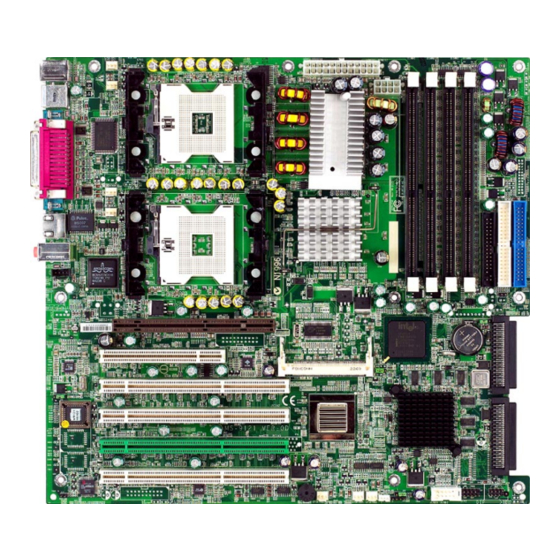
BCM5703CKHB JCD1 JCI1 AGP Pro Slot JBAT1 BATT ICH4 PCI 1 PCI 2 Codec PCIX1 PCIX2 BIOS P64H2 LSI53C1030 PCIX3 PCIX4 SYSFAN3 JUSB3 JFP2 JFP3 SYSFAN5 SYSFAN4 JWL1 J18 E7505 Master-LS2 (MS-9121 v1.X) E-ATX Mainboard This manual downloaded from http://www.manualowl.com... -
Page 13: Msi Special Features
MS-9121 E-ATX Mainboard MSI Special Features PC Alert™ III The PC Alert III is a utility you can find in the CD-ROM disk. The utility is just like your PC doctor that can de- tect the following PC hardware status during real time operation: monitor CPU &... -
Page 14: Live Bios™/Live Driver
BIOS/drivers online so that you don’t need to search for the correct BIOS/driver version throughout the Web site. To use the function, you need to install the “MSI Live Update 2” application. After the installation, the “MSI Live Update 2” icon (as shown on the right) will appear on the screen. -
Page 15: Live Monitor
Live Monitor™ The Live Monitor™ is a tool used to schedule the search for the latest BIOS/drivers version on the MSI Web site. To use the function, you need to install the “MSI Live Update 2” application. After installation, the “MSI Live Monitor” icon (as shown on the right) will appear on the screen. -
Page 16: Chapter 2. Hardware Setup
Hardware Setup Chapter 2. Hardware Setup Hardware Setup This chapter provides you with the information about hard- ware setup procedures. While doing the installation, be careful in holding the components and follow the installation procedures. For some components, if you install in the wrong orientation, the components will not work properly. -
Page 17: Quick Components Guide
MS-9121 E-ATX Mainboard Quick Components Guide CPU, p.2-3 CPUFAN1 POWER1, p.2-8 SYSFAN1, p.2-16 POWER2, p.2-8 DIMM1~4, p.2-6 FDD1, p.2-14 Back Panel I/O, p.2-9 IDE1/2, p.2-15 CPUFAN2 SYSFAN2, p.2-16 JCD1, p.2-19 JCI1, p.2-14 JBAT1, p.2-21 AGP Pro, p.2-25 J12, p.2-22 SCSI 1 J14, p.2-23 SCSI 2, p.2-20... -
Page 18: Central Processing Unit: Cpu
Hardware Setup Central Processing Unit: CPU ® The mainboard supports Single/Dual Intel Xeon™ processors and uses two CPU sockets called Socket 604 for easy CPU installation. You can install SINGLE or DUAL CPUs on the board to meet your own needs. Keep the following points in mind before installing CPU(s): 1. -
Page 19: Cpu Installation Procedures
MS-9121 E-ATX Mainboard CPU Installation Procedures Open Lever 1. Please turn off the power and unplug the power cord before installing the CPU. Sliding Plate 2. Pull the lever sideways away from the socket. Make sure to raise the lever up to a 90-de- gree angle. -
Page 20: Cpu Core Speed Derivation Procedure
CPU core speed Host Clock x Core/Bus ratio 100MHz x 14 1.4 GHz MSI Reminds You... Overheating Overheating will seriously damage the CPU and system, al- ways make sure the cooling fan can work properly to protect the CPU from overheating. -
Page 21: Memory
MS-9121 E-ATX Mainboard Memory The mainboard provides 4 slots for 184-pin DDR DIMM (Double In- Line Memory Module) modules and supports the memory size up to 8 GB. You can install PC2100/DDR266 or PC1600/DDR200 DDR SDRAM mod- ules on the DDR DIMM slots (DIMM 1~4). DDR DIMM Slots (DIMM 1~4) Memory Speed/CPU FSB Support Matrix... -
Page 22: Installing Ddr Modules
128MB~2GB 128MB~2GB 128MB~2GB 128MB~2GB 512MB~8GB MSI Reminds You... Make sure that you install memory modules of the same type and density on DDR DIMMs “in pairs” -- {DIMM1 & DIMM2} {DIMM3 & DIMM4}. Installing DDR Modules 1. The DDR DIMM has only one notch on the center of module. The mod- ule will only fit in the right orientation. -
Page 23: Power Supply
MS-9121 E-ATX Mainboard Power Supply The mainboard supports SSI power supply for the power system. Be- fore inserting the power supply connector, always make sure that all compo- nents are installed properly to ensure that no damage will be caused. SSI 24-Pin Power Connector: POWER1 This connector allows you to connect to an SSI power supply. -
Page 24: Back Panel
Hardware Setup Back Panel The back panel provides the following connectors: Parallel Mouse L-In L-Out Keyboard COM A COM B Mouse Connector ® The mainboard provides a standard PS/2 mouse mini DIN connector for attaching a PS/2 ® mouse. You can plug a PS/2 ®... -
Page 25: Keyboard Connector
MS-9121 E-ATX Mainboard Keyboard Connector ® The mainboard provides a standard PS/2 keyboard mini DIN connec- ® ® tor for attaching a PS/2 keyboard. You can plug a PS/2 keyboard directly into this connector. Pin Definition SIGNAL DESCRIPTION Keyboard DATA Keyboard DATA No connection Ground... -
Page 26: Serial Port Connector: Com A & Com B
Hardware Setup Serial Port Connector: COM A & COM B The mainboard offers two 9-pin male DIN connectors as serial port COM A and COM B. The ports are 16550A high speed communication ports that send/receive 16 bytes FIFOs. You can attach a serial mouse or other serial devices directly to them. -
Page 27: Parallel Port Connector: Lpt1
MS-9121 E-ATX Mainboard Parallel Port Connector: LPT1 The mainboard provides a 25-pin female centronic connector as LPT. A parallel port is a standard printer port that supports Enhanced Parallel Port (EPP) and Extended Capabilities Parallel Port (ECP) mode. Pin Definition SIGNAL DESCRIPTION STROBE... -
Page 28: Rj-45 Lan Jack: Giga-Bit Lan
Hardware Setup RJ-45 LAN Jack: Giga-bit LAN The mainboard provides one standard RJ-45 jack for connection to Local Area Network (LAN). Giga-bit LAN enables data to be transferred at 1000, 100 or 10Mbps. Pin assignments vary depending on the transfer rates: 10/100Mbps or 1000Mbps. -
Page 29: Connectors
MS-9121 E-ATX Mainboard Connectors The mainboard provides connectors to connect to FDD, IDE HDD, case, modem, LAN, USB Ports, IR module and CPU/System/Power Supply FAN. Floppy Disk Drive Connector: FDD1 The mainboard provides a standard floppy disk drive connector that supports 360K, 720K, 1.2M, 1.44M and 2.88M floppy disk types. -
Page 30: Hard Disk Connectors: Ide1/2
IDE2 (Secondary IDE Connector) IDE2 can also connect a Master and a Slave drive. MSI Reminds You... If you install two hard disks on cable, you must configure the second drive to Slave mode by setting its jumper. Refer to the hard disk documentation supplied by hard disk vendors for jumper setting instructions. -
Page 31: Fan Power Connectors: Cpufan1/2, Sysfan1/2/3/4/5
Hardware Monitor chipset on-board, you must use a specially designed fan with speed sensor to take advantage of the CPU fan control. SYSFAN1 CPUFAN1 CPUFAN2 SYSFAN2 SYSFAN5 SYSFAN4 SYSFAN3 MSI Reminds You... Always consult the vendors for proper CPU cooling fan. 2-16 This manual downloaded from http://www.manualowl.com... -
Page 32: Front Panel Connectors: Jfp2, Jfp3
Hardware Setup Front Panel Connectors: JFP2, JFP3 The mainboard provides two front panel connectors for electrical con- nection to the front panel switches and LEDs. The JFP2 is compliant with ® Intel Front Panel I/O Connectivity Design Guide. Power Power Switch JFP2 Reset... -
Page 33: Scsi Led Connector: J18
MS-9121 E-ATX Mainboard SCSI LED Connector: J18 Connect the J18 to the LED connector on the add-on SCSI adaptor and the HDD LED will blink when add-on SCSI device is active. Pin Definition SIGNAL VCC5 SCSI LED HDD LED VCC5 Front USB Connector: JUSB3 The mainboard provides one front Universal Serial Bus connector for users to connect optional USB ports. -
Page 34: Wake On Lan Connector: Jwl1
LAN function. You can wake up the computer via remote control through a local area network. MP_WAKEUP 5VSB JWL1 MSI Reminds You... To be able to use this function, you need a power supply that provides enough power for this feature. (750 mA 5V Stand-by) 2-19 This manual downloaded from http://www.manualowl.com... -
Page 35: Ultra320 Scsi Connectors: Scsi 1/2
MS-9121 E-ATX Mainboard Ultra320 SCSI Connectors: SCSI 1/2 SCSI (Small Computer System Interface) is a hardware interface that allows for connection of up to 15 peripheral devices. The mainboard pro- vides onboard dual SCSI channels (SCSI 1 & SCSI 2) for you to connect SCSI devices such as SCSI hard disks. -
Page 36: Jumpers
JBAT1 Keep Data Clear Data MSI Reminds You... You can clear CMOS by shorting 2-3 pin while the system is off. Then return to 1-2 pin position. Avoid clearing the CMOS while the system is on; it will damage the mainboard. -
Page 37: System Configure Jumper: J12
MS-9121 E-ATX Mainboard System Configure Jumper: J12 The J12 jumper determines which mode the system will enter while powered on. During Normal Mode, the system will enter the assigned OS as usual. During Configure Mode, the system will directly enter BIOS setup utility. -
Page 38: Bios Flash Jumper: J14
Hardware Setup BIOS Flash Jumper: J14 This jumper is used to protect the BIOS boot block from virus infection. When locked, the BIOS boot block cannot be accessed, making BIOS update impossible. When BIOS update is intended, short pin 2 & 3 to disable BIOS flash protection. -
Page 39: Asr Enable/Disable Jumper: J17
MS-9121 E-ATX Mainboard ASR Enable/Disable Jumper: J17 This jumper is used to enable/disable the ASR (Auto Server Reboot) function. Disable ASR Enable ASR 2-24 This manual downloaded from http://www.manualowl.com... -
Page 40: Slots
Hardware Setup Slots The motherboard provides one AGP Pro slot, one 32-bit Master PCI slot, one Mini PCI slot, and four 64-bit PCI-X slots. AGP Pro Slot 32-bit PCI Slot 64-bit PCI-X Slots Mini PCI Slot AGP (Accelerated Graphics Port) Pro Slot The AGP Pro slot allows you to insert the AGP/AGP Pro graphics card. - Page 41 (at an angle of 45 degrees) into the slot until the golden finger of the card gets fully inserted into the slot. MSI Reminds You... You can barely see the golden finger if the card is properly inserted in the socket.
- Page 42 Hardware Setup 3. Locate the supporters on the mainboard (one on the right end and the other on the left end). Align the two fixing holes on the card with the sup- porters and press the card carefully down until the fixing holes get locked supporters by the supporters.
- Page 43 MS-9121 E-ATX Mainboard 2. Clip the other supporter and press it downwards until it withdraws from the fixing hole. supporter 3. The card will automatically bound upwards after being released from the supporters. 4. Remove the card from the Mini PCI slot.
-
Page 44: Interrupt Request Routing
Hardware Setup Interrupt Request Routing The IRQ, acronym of interrupt request line and pronounced I-R-Q, are hardware lines over which devices can send interrupt signals to the microprocessor. DEVICE INT A# INT B# INT C# INT D# PIRQA_L PIRQB_L PCI Slot 1 PIRQF_L PIRQG_L PIRQH_L... -
Page 45: Chapter 3. Bios Setup
BIOS Setup Chapter 3. BIOS Setup BIOS Setup This chapter provides information on the BIOS Setup pro- gram and allows you to configure the system for optimum use. You may need to run the Setup program when: An error message appears on the screen during the system booting up, and requests you to run SETUP. -
Page 46: Entering Setup
MS-9121 E-ATX Mainboard Entering Setup Power on the computer and the system will start POST (Power On Self Test) process. When the message below appears on the screen, press <DEL> key to enter Setup. Press DEL to enter SETUP If the message disappears before you respond and you still wish to enter Setup, restart the system by turning it OFF and On or pressing the RESET button. -
Page 47: Getting Help
Press <Esc> to exit the Help screen. MSI Reminds You... The items under each BIOS category described in this chapter are under continuous update for better system performance. -
Page 48: The Main Menu
MS-9121 E-ATX Mainboard The Main Menu Once you enter Award Workstation BIOS CMOS Setup Utility, the Main Menu will appear on the screen. The Main Menu displays twelve configurable functions and two exit choices. Use arrow keys to move among the items and press <Enter>... - Page 49 BIOS Setup PNP/PCI Configurations This entry appears if your system supports PnP/PCI. PC Health Status This entry shows your PC health status. Frequency/Voltage Control Use this menu to specify your settings for frequency/voltage control. Load Fail-Safe Defaults Use this menu to load the BIOS default values for minimal but stable system performance.
-
Page 50: Standard Cmos Features
MS-9121 E-ATX Mainboard Standard CMOS Features The items inside Standard CMOS Features menu are divided into 10 categories. Each category includes none, one or more setup items. Use the arrow keys to highlight the item you want to modify and use the <PgUp> or <PgDn>... - Page 51 BIOS Setup will not work properly if you enter improper information for this category. If your hard disk drive type is not matched or listed, you can use Manual to define your own drive type manually. If you select Manual, related information is asked to be entered to the follow- ing items.
-
Page 52: Advanced Bios Features
MS-9121 E-ATX Mainboard Advanced BIOS Features Virus Warning The item is to set the Virus Warning feature for IDE Hard Disk boot sector protection. If the function is enabled and any attempt to write data into this area is made, BIOS will display a warning message on screen and beep. Set- ting options: Disabled, Enabled. - Page 53 Setting options: Enabled, Disabled. MSI Reminds You... Enabling the functionality of Hyper-Threading Technology for your computer system requires ALL of the following platform...
- Page 54 MS-9121 E-ATX Mainboard Boot Other Device Setting the option to Enabled allows the system to try to boot from other devices if the system fails to boot from the 1st/2nd/3rd boot device. Swap Floppy Drive Setting to Enabled will swap floppy drives A: and B:. Boot Up Floppy Seek This setting causes the BIOS to search for floppy disk drives at boot time.
- Page 55 BIOS Setup Typematic Delay (Msec) This item allows you to select the delay between when the key was first pressed and when the acceleration begins. Settings: 250, 500, 750 and 1000. Security Option This specifies the type of BIOS password protection that is implemented. Set- tings are described below: Option Description...
-
Page 56: Advanced Chipset Features
MS-9121 E-ATX Mainboard Advanced Chipset Features MSI Reminds You... Change these settings only if you are familiar with the chipset. DRAM Timing Control Press <Enter> to enter the sub-menu and the following screen appears: DRAM Timing Configure This setting determines whether DRAM timing is configured by reading... - Page 57 BIOS Setup module. Selecting By SPD makes the following settings automatically determined by BIOS according to the configurations on the SPD. Setting options: By SPD, Manual. CAS Latency Time This setting controls the timing delay (in clock cycles) before SDRAM starts a read command after receiving it.
- Page 58 MS-9121 E-ATX Mainboard C7FFFh, resulting in better video performance. However, if any program writes to this memory area, a system error may result. Setting options: Disabled, Enabled. Memory Hole At 15M-16M In order to improve performance, certain space in memory can be reserved for ISA cards.
-
Page 59: Integrated Peripherals
BIOS Setup Integrated Peripherals Super IO Device Press <Enter> to enter the sub-menu and the following screen appears: Onboard FDC Controller Select Enabled if your system has a floppy disk controller (FDD) in- stalled on the system board and you wish to use it. If you install add-on FDC or the system has no floppy drive, select Disabled in this field. - Page 60 MS-9121 E-ATX Mainboard serial ports. The settings are: 3F8/IRQ4, 2E8/IRQ3, 3E8/IRQ4, 2F8/IRQ3, Disabled, Auto. UART Mode Select This setting allows you to specify the operation mode for serial port 2. Setting options: Standard, IrDA SIR, Sharp IR. Standard RS-232C Serial Port IrDA SIR IrDA-compliant Serial Infrared Port Sharp IR...
- Page 61 BIOS Setup Leaves the computer in the power off state. Reboots the computer. Former-Sts Restores the system to the status before power failure or interrupt occurs. OnChip IDE Device Press <Enter> to enter the sub-menu and the following screen appears: IDE HDD Block Mode This allows your hard disk controller to use the fast block mode to trans- fer data to and from the hard disk drive.
- Page 62 MS-9121 E-ATX Mainboard it and your operating environment contains a DMA driver. If both your hard drive and software support Ultra DMA 33 (or higher), select Auto to enable BIOS support. Onboard Device Press <Enter> to enter the sub-menu and the following screen appears: USB Controller Select Enabled if your system contains a Universal Serial Bus (USB) controller and you have USB peripherals.
-
Page 63: Power Management Setup
BIOS Setup Power Management Setup MSI Reminds You... S3-related functions described in this section are available only when your BIOS supports S3 sleep mode. ACPI Suspend Type This setting specifies the power saving mode for ACPI function if your oper- ating system supports ACPI, such as Windows 98SE, Windows ME and Win- dows 2000. - Page 64 MS-9121 E-ATX Mainboard Video Off Method This determines the manner in which the monitor is blanked. V/H SYNC+Blank This selection will cause the system to turn off the vertical and horizontal synchronization ports and write blanks to the video buffer. Blank Screen This option only writes blanks to the video buffer.
- Page 65 Setting options: Enabled, Disabled. MSI Reminds You... You need to install a modem card supporting power on function for “Power On by Ring” function.
-
Page 66: Pnp/Pci Configurations
MS-9121 E-ATX Mainboard PNP/PCI Configurations This section describes configuring the PCI bus system and PnP (Plug & Play) feature. PCI, or Peripheral Component Interconnect, is a system which allows I/O devices to operate at speeds nearing the speed the CPU itself uses when communicating with its special components. - Page 67 BIOS Setup IRQ Resources The items are adjustable only when Resources Controlled By is set to Manual. Press <Enter> and you will enter the sub-menu of the items. IRQ Resources list IRQ 3/4/5/7/9/10/11/12/14/15 for users to set each IRQ a type depending on the type of device using the IRQ.
-
Page 68: Pc Health Status
MS-9121 E-ATX Mainboard PC Health Status This section shows the status of your CPU, fan, overall system status, etc. Monitor function is available only if there is hardware monitoring mecha- nism onboard. Case Open Warning The field enables or disables the feature of recording the chassis intrusion status and issuing a warning message if the chassis is once opened. -
Page 69: Frequency/Voltage Control
BIOS Setup Frequency/Voltage Control Use this menu to specify your settings for frequency/voltage control. CPU Clock Ratio This setting controls the multiplier that is used to determine the internal clock speed of the processor relative to the external or motherboard clock speed. Auto Detect DIMM/PCI Clk This setting is used to auto detect the DIMM/PCI slots. -
Page 70: Load Fail-Safe/Optimized Defaults
MS-9121 E-ATX Mainboard Load Fail-Safe/Optimized Defaults The two options on the main menu allow users to restore all of the BIOS settings to the default Fail-Safe or Optimized values. The Optimized Defaults are the default values set by the mainboard manufacturer specifically for op- timal performance of the mainboard. -
Page 71: Set Supervisor/User Password
FEATURES menu. If the Security Option is set to System, the password is required both at boot and at entry to Setup. If set to Setup, password prompt only occurs when you try to enter Setup. MSI Reminds You... About Supervisor Password & User Password: Supervisor password: Can enter and change the settings of the setup menu. -
Page 72: Troubleshooting
Q: How do I know what MSI D-LED or D-bracket light mean? A: Please follow the special tech issue, http://www.msi.com.tw/support/ techexpress/special_tech/smartled.htm Q: I used my MSI motherboard and got an error message, "Primary IDE Channel No 80 Conductor Cable Installed" while the system detected hard drives. - Page 73 2. Try to clear the CMOS If problem still persists, ask your reseller for new BIOS chip or contact one of MSI office near your place for new BIOS chip http:// www.msi.com.tw/contact/main.htm Q: Should I update my BIOS, once a new BIOS is released? A: A new BIOS is usually released due to the following reasons: 1.
- Page 74 BIOS, unless you really have to. Q: How do I update the BIOS? A: Please refer to http://www.msi.com.tw/support/bios/note.htm for details. Q: How do I identify the BIOS version? A: Upon boot-up, the 1st line appearing after the memory count is the BIOS version.
- Page 75 MS-9121 E-ATX Mainboard Q: After I flashed the BIOS and rebooted the system, the screen went blank. A: For AMI BIOS Rename the desired AMI BIOS file to AMIBOOT.ROM and save it on a floppy disk. e.g. Rename A569MS23.ROM to AMIBOOT.ROM Insert this floppy disk in the floppy drive.
-
Page 76: Glossary
Glossary Glossary Glossary ACPI (Advanced Configuration & Power Interface) This power management specification enables the OS (operating system) to control the amount of power given to each device attached to the computer. Windows 98/98SE, Windows 2000 and Windows ME can fully support ACPI to allow users managing the system power flexibly. - Page 77 MS-9121 E-ATX Mainboard contents of frequently accessed RAM locations and the addresses where these data items are stored. Chipset A collection of integrated chips designed to perform one or more related functions. For example, a modem chipset contains all the primary circuits for transmitting and receiv- ing data;...
- Page 78 Glossary ECC Memory (Error Correcting Code Memory) A type of memory that contains special circuitry for testing the accuracy of data and correcting the errors on the fly. EEPROM Acronym for Electrically Erasable Programmable Read-Only Memory. An EEPROM is a special type of PROM that can be erased by exposing it to an electrical charge. Like other types of PROM, EEPROM retains its contents even when the power is turned off.
- Page 79 MS-9121 E-ATX Mainboard IDE (Integrated Drive Electronics) A type of disk-drive interface widely used to connect hard disks, CD-ROMs and tape drives to a PC, in which the controller electronics is integrated into the drive itself, eliminating the need for a separate adapter card. The IDE interface is known as the ATA (AT Attachment) specification.
- Page 80 Glossary LBA (Logical Block Addressing) Logical block addressing is a technique that allows a computer to address a hard disk larger than 528 megabytes. A logical block address is a 28-bit value that maps to a specific cylinder-head-sector address on the disk. 28 bits allows sufficient variation to specify addresses on a hard disk up to 8.4 gigabytes in data storage capacity.
- Page 81 MS-9121 E-ATX Mainboard PS/2 Port A type of port developed by IBM for connecting a mouse or keyboard to a PC. The PS/2 port supports a mini DIN plug containing just 6 pins. Most modern PCs equipped with PS/2 ports so that the special port can be used by another device, such as a modem.
Need help?
Do you have a question about the E7505 Master-LS2 and is the answer not in the manual?
Questions and answers