Page 1
Instruction Handbook for VM Series Machining Centers Milltronics Manufacturing Company 1400 Mill Lane Waconia, MN 55387 USA Phone 952-442-1410 Fax 952-442-6457 www.milltronics.net Rev 9-17-2013...
NSTRUCTION ANDBOOK 1973 ERVING THE ETAL UTTING NDUSTRY INCE • W 1400 M , MN 55387 ACONIA : 952.442.6455 • F : 952.442.6457 Table Of Contents Chapter 1 - Safety ......................1 Safety Checklist......................2 Basic Points Of Safety....................2 Clothing and Personal Safety..................
Page 5
On / Off Timer Settings....................43 Automatic Tool Changer (ATC) Maintenance............. 44 Drawbar cylinder Maintenance (Inline spindle models only)........45 Chapter 7 – 8200 CNC Operation ................. 47 Milltronics 8200 CNC Front Panel ................47 Power ON........................47 Power OFF ......................... 47...
Chapter 1 - Safety The general principles for safe operation of Milltronics machines are outlined in this manual. Every Milltronics machine is engineered for safety. You will note, for example, that all rotating parts are protected by specially designed covers. On some models, the...
Safety Checklist • Always observe the safety instructions inscribed on the safety labels fixed onto the machine. Do not remove or alter these labels. • Do not attempt to operate this machine until you have read the manuals supplied with the machine and understand each of the functions and operation methods. •...
• Do not subject the CNC control unit, the operator’s panel, or the electrical control panel to strong voltage fluctuations. • Do not change any machine parameter values without consulting Milltronics service department. If it becomes necessary to change a value, first check if it is safe to do so, then make a note of the original value so it can be reset if necessary.
Page 10
• Always use safety shoes with steel toecaps and oil resistant soles. • Do not operate the machine while wearing loose or baggy clothes. • Always completely fasten buttons and hooks on the arms of clothing to avoid danger of entanglement in machine mechanisms. •...
1 - S HAPTER AFETY Safety Related to Workpiece Machining And Tooling 1. DANGER • Never operate the spindle above the rated speed of accessories mounted on it (chucks, tooling, etc). • Do not extend stock out of a lathe headstock without an appropriate bar feed or support.
• Ensure all hardware is tight and properly torqued after performing maintenance operations. See torque specifications in chapter 2. Electrical Safety Read and understand the following list of cautions before attempting to perform service on this equipment. Failure to observe these rules can result in death or serious injury.
1 - S HAPTER AFETY Maintenance should not be performed on a machine under power. For even the most routine day-to-day maintenance, such as cleaning the table or removing chips from the machining enclosure, the machine should be put in an emergency stop condition, de- energizing the axis servo motors and spindle motor.
Safety and Maintenance Label Locations and Descriptions Item Description Page Danger and Safety Precaution Projectile Hazard Chip Auger/Conveyor Hazard Main Power hazard and Notice ATC crush hazard Auger warning Warmup and daily checks Spindle Operation and Precaution Drawbar Maintenance (if equipped) For Inline spindle models only Waylube maintenance Air system maintenance ATC maintenance...
Page 15
1 - S HAPTER AFETY Read and understand all Safety, Operation, and Maintenance labels affixed to the machine to ensure safety and reliability. Located near access doors on models equipped with full enclosure. Located around hazard areas on models equipped with chip conveyor. Located around hazard areas on models equipped with chip auger.
Page 16
Located near main power disconnect switch on all models. Located near Automatic Tool Changers and other potential crush hazard areas. Located on chip auger chute if equipped. All models, located near operator station. Perform all checks to prevent damage and ensure reliable operation. All models, located near operator station.
Page 17
1 - S HAPTER AFETY Maintenance labels located on machine near maintenance items. Various labels are used depending on options/equipment. Maintenance labels located on machine near maintenance items. Various labels are used depending on options/equipment. Maintenance labels located on machine near maintenance items.
• Thickness for VM15, 16, 20 models must be at least 4” • Thickness for VM22, 25, 30 models must be at least 6” Milltronics will not guarantee machine geometry unless this is adhered to. 2. Ample ceiling height, and clearance behind the machine to fully open the door of the electrical cabinet at the rear of the machine.
4. Milltronics does not allow the use of a separate grounding rod. 5. Milltronics does not allow conduit or wire raceways be used as a ground. 6. If a transformer is used to step the voltage down to 220 refer to the transformer grounding procedures immediately following this page.
4 - I HAPTER NSTALLATION Connecting a Transformer It is important that proper grounding procedures be followed when hooking up machines to power. Please review the following pages. They explain proper transformer connections and checks to ensure proper connections. Refer to the autotransformer diagram provided to verify that your connections are suitable.
Autotransformer Connection Diagram If your machine was ordered from Milltronics with a transformer option an autotransformer is supplied. The diagram below illustrates the various input voltage selections and proper ground wire connections. Always call the factory if in doubt concerning transformer connections as serious...
HAPTER NSTALLATION Air Supply System Milltronics machining centers require a constant supply of quality air pressure in order to perform optimally. 90-110 PSI at 10 CFM is required for VM15 through VM30 models. Adjustments • Set the main air regulator to 90 PSI.
Lifting By forklift This machine should only be moved, loaded/unloaded, or skidded/unskidded by a trained and certified machine mover. Instruction • Approach the machine from any side. • Spread forks as wide as possible. • Beware of cables, wires, and other hardware. •...
4 - I HAPTER NSTALLATION Lifting By Crane or Hoist This machine should only be moved, loaded/unloaded, or skidded/unskidded by a trained and certified machine mover.
Startup checklist The enclosed startup checklist guides the process of the machine installation and checkout. The startup checklist forms must be completed and sent to Milltronics Mfg. to activate the machine warranty. Use the startup checklist in conjunction with the following outline when installing and setting up the machine.
Page 35
4 - I HAPTER NSTALLATION If the enclosure end pieces were removed for shipping install them as shown. Enclosure end Piece, Each side. Install or adjust the Z-axis cable track as shown. In many cases this track is loosened or removed for shipping.
Page 36
Once the machine is in place and assembled this far, have the power and air supplies connected by qualified personnel as described in chapter 1. See the safety checklist on page 2 for qualifications Level the machine (rough level) in both side to side and front to back directions.
Note: This procedure is duplicated as part of the startup checklist enclosed. Please make note of the final tram readings on the startup checklist forms to be returned to Milltronics. 1. Center the table in the travels of both the X and the Y-axes.
Initial Checks of the Machine, its Guards and Safety Systems General Checks 1. Check for missing parts. Do not operate the machine if parts are missing. 2. Visually check for damage outside of machine and inside. Do not operate the machine if there has been shipping damage.
4 - I HAPTER NSTALLATION WARNING: DANGEROUS VOLTAGES EXIST FOR THE VOLTAGE LEVEL CHECKS! 2. Check voltage levels. As stated in the Electrical Safety Rules, only qualified personnel should attempt to take these measurements. With the electrical cabinet door open, turn on the main power at the disconnect switch. Do not reset the drives, i.e.
Safety Checks Follow the sequences outlined below for Centurion control. Home the Machine During this operation, the machine will move. Before starting the operation, make sure any shipping clamps that might impede machine movement have been removed and nothing else remains to interfere with machine motion. Turn main power on.
4 - I HAPTER NSTALLATION Spindle rotation should stop. The emergency stop button is the most important safety switch on the machine. It stops and then de-energizes the spindle motor. (At the same time, it stops and de-energizes the axis servo motors, although they are not running for this test.) When the red emergency stop button is pushed, the spindle should brake to a rapid stop.
Spindle Start up Procedure Daily Run-in procedure 1. Start the flood pump or chiller unit (if equipped) and run coolant through coolant passages until the temperature stabilizes. 2. Clamp a tool holder into the spindle. Never operate the spindle without a tool holder installed.
Chapter 5 - Failure Modes, Detection and Prevention Minimizing Wear and Tear • The effects of everyday wear and tear may be minimized by good maintenance practice. Items high on the maintenance list include keeping the machine clean, providing clean dry compressed air with the correct oil drip into the air stream, and continuous application of the correct way oil through the automatic oiler.
• When an electrical component needs to be replaced, follow the guidelines in this manual describing safe maintenance practice. Diagnosing Mechanical Faults • Eyes, ears and hands are the best tools for detecting mechanical failure modes. As is the case for electrical faults, an accidental crash between tool and workpiece is a likely way to cause mechanical damage.
Chapter 6 – Maintenance Periodic Maintenance; Verification Of Safety Systems Note: Before performing any of the procedures in this section, please read and follow the directions in this manual covering safe practices for operation, setting and maintenance. Maintenance operations should only be performed by qualified personnel as described in chapter 1.
Weekly • Check operation of all cooling fans. • Check for proper air exhaust from the spindle air purge system (if equipped). • Clean any chips from on top of the ATC carousel and ATC slides. Monthly • Grease the machine per instructions in the manual (unless equipped with Autolube), detailed specifications can be found in the mechanical manual.
6 - MAINTENANCE HAPTER Annually • Check backlash to ensure proper axis motion and response. • Check head tram to ensure proper machine geometry. Machine settling can cause tram to be out of specification, affecting machine geometry. • Clean the intake screen on the way lube pump. •...
• Set the main air regulator to 90 PSI. • Do not adjust the air purge regulator unless instructed to do so by an authorized Milltronics Representative. • Set the drop rate on the lubricator to approximately 1 drop per every 1-2 tool changes.
6 - MAINTENANCE HAPTER Way Lube Maintenance • Ensure the way lube reservoir level is maintained (if equipped). (Use Mobil Vactra No. 02, Amoco Waytec No 68, Sunoco Sunwaylube No1180, or equivalent oil, more details found in mechanical manual). • Clean the intake filter screen annually. •...
Automatic Tool Changer (ATC) Maintenance Check ATC fluid level here. 24,32,40 Pocket Arm style ATC. Monitor sight glass to ensure fluid level remains topped off. Replace oil annually with Mobilgear ISO 150 or equivalent gear oil. Drain plug 16 or 24 Pocket carousel style ATC Lubrication is automatic via the lubrication system on the machine.
Chapter 7 – 8200 CNC Operation Milltronics 8200 CNC Front Panel 3 4 5 Power ON The main power switch is located on the electrical cabinet at the back of the machine. When main power is switched on, the power to the CNC is also applied.
Page 54
Manual Pulse Generator (HANDWHEEL) - rotate this wheel to control axis feed while in HDW mode. 1) FEEDRATE override rotary switch - labeled in percentages. Controls the feedrate and rapid traverse (Exception - see #3) of the machine axes. Also affects handwheel rate.
Page 55
7 8200 CNC OPERATIONS HAPTER 7) SPINDLE CW/STOP/CCW o Spindle CW button – starts spindle in clockwise direction provided there is a programmed spindle rpm. o Spindle CCW button – starts spindle in counter-clockwise direction provided there is a programmed spindle rpm. o Spindle STOP button –...
Need help?
Do you have a question about the VM Series and is the answer not in the manual?
Questions and answers
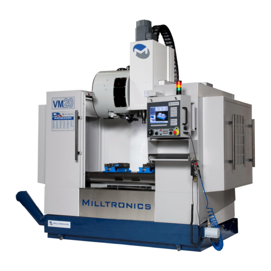
we just received a milltronics vm 4020. i would like to get lifting instructions. we do have the lifting bracket.