Table of Contents
Advertisement
Quick Links
Advertisement
Table of Contents

Related Manuals for Gigabyte GA-990FX-Gaming


Summary of Contents for Gigabyte GA-990FX-Gaming
- Page 1 GA-990FX-Gaming User's Manual Rev. 1002 12ME-990FXGM-1002R For more product details, please visit GIGABYTE's website. To reduce the impacts on global warming, the packaging materials of this product are recyclable and reusable. GIGABYTE works with you to protect the environment.
- Page 2 The trademarks mentioned in this manual are legally registered to their respective owners. Disclaimer Information in this manual is protected by copyright laws and is the property of GIGABYTE. No part of this manual may be reproduced, copied, translated, transmitted, or published in any form or by any means without GIGABYTE's prior written permission.
-
Page 3: Table Of Contents
Table of Contents GA-990FX-Gaming Motherboard Layout .................4 Chapter 1 Hardware Installation ..................5 Installation Precautions ..................5 ..................6 Installing the CPU .................... 9 Installing the Memory ..................9 Installing an Expansion Card ................. 10 Back Panel Connectors .................. 10 Onboard Buttons and Switch ................. 12 ............... -
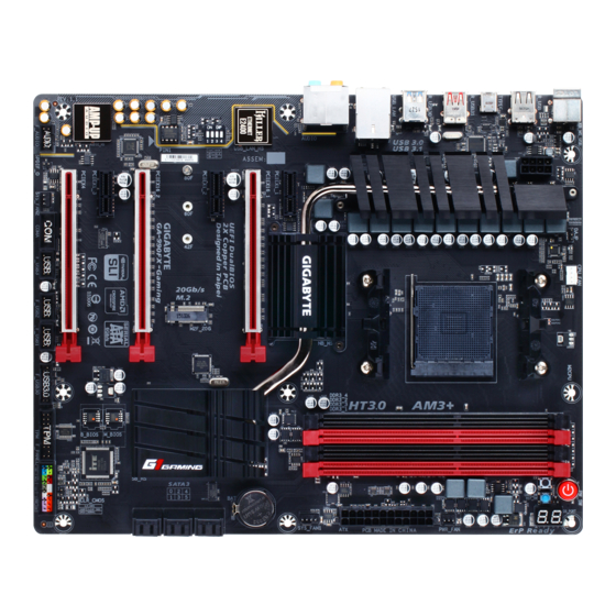
Page 4: Ga-990Fx-Gaming Motherboard Layout
GA-990FX-Gaming Motherboard Layout (Note) PW_SW CPU_FAN KB_MS_USB ATX_12V Socket AM3+ TYPEC ASMedia ® USB 3.1 Controller USB_LAN PCIEX1_1 SYS_FAN1 PCIEX16_1 Killer ™ E2201 LAN PCIEX1_2 GAIN TI Burr Brown ® OPA2134 SATA3 PCIEX16_2 ® VL805 GA-990FX-Gaming PCIEX1_3 M_BIOS ® Super I/O... -
Page 5: Chapter 1 Hardware Installation
Chapter 1 Hardware Installation Installation Precautions The motherboard contains numerous delicate electronic circuits and components which can become manual and follow these procedures: Prior to installation, make sure the chassis is suitable for the motherboard. Prior to installation, do not remove or break motherboard S/N (Serial Number) sticker or warranty sticker provided by your dealer. - Page 6 5200 MT/s Chipset Memory memory is installed, the actual memory size displayed will be less than the size of the physical memory installed. (Go to GIGABYTE's website for the latest supported memory speeds and memory modules.) Audio ® ALC1150 codec ®...
- Page 7 South Bridge: 12 x USB 2.0/1.1 ports (6 ports on the back panel, 6 ports available through the internal USB headers) ® VL805 chip: 4 x USB 3.0/2.0 ports (2 ports on the back panel, 2 ports available through the internal USB header) ASMedia ®...
- Page 8 System Form Factor ATX Form Factor; 30.5cm x 24.4cm prior notice. Please visit GIGABYTE's website Please visit the Support\Utility List for support lists of CPU, memory page on GIGABYTE's website to download the latest version of apps. - 8 -...
-
Page 9: Installing The Cpu
Make sure that the motherboard supports the memory. It is recommended that memory of the same capacity, brand, speed, and chips be used. (Go to GIGABYTE's website for the latest supported memory speeds and memory modules.) Always turn off the computer and unplug the power cord from the power outlet before installing the memory to prevent hardware damage. -
Page 10: Installing An Expansion Card
2 Modules 4 Modules of the same capacity, brand, speed, and chips be used and installed in the same colored sockets. For Installing an Expansion Card Make sure the motherboard supports the expansion card. Carefully read the manual that came with your expansion card. - Page 11 If you want to install a Side Speaker, you need to retask either the Line in or Mic in jack to be Side Speaker out through the audio driver. Please visit GIGABYTE's website for more software information. device and then remove it from the motherboard.
-
Page 12: Onboard Buttons And Switch
Onboard Buttons and Switch Quick Buttons This motherboard has 3 quick buttons: power button, reset button and clear CMOS button. The power button and reset button allow users to quickly turn on/off or reset the computer in an open-case environment when they want to change hardware components or conduct hardware testing. -
Page 13: Internal Connectors
Internal Connectors ATX_12V F_AUDIO SPDIF_O CPU_FAN F_USB30 SYS_FAN1/2 F_USB1/F_USB2/F_USB3 PWR_FAN COMA SATA3 0/1/2/3/4/5 M2F_20G F_PANEL CLR_CMOS First make sure your devices are compliant with the connectors you wish to connect. Before installing the devices, be sure to turn off the devices and your computer. Unplug the power cord from the power outlet to prevent damage to the devices. - Page 14 1/2) ATX_12V/ATX (2x4 12V Power Connector and 2x12 Main Power Connector) With the use of the power connector, the power supply can supply enough stable power to all the components off and all devices are properly installed. The power connector possesses a foolproof design. Connect the power supply cable to the power connector in the correct orientation.
- Page 15 3/4/5) CPU_FAN/SYS_FAN1/SYS_FAN2/PWR_FAN (Fan Headers) The motherboard has a 4-pin CPU fan header (CPU_FAN), a 4-pin (SYS_FAN1) and a 3-pin (SYS_FAN2) insertion design. When connecting a fan cable, be sure to connect it in the correct orientation (the black connector wire is the ground wire). The speed control function requires the use of a fan with fan speed control design.
- Page 16 7) M2F_20G (M.2 Socket 3 Connector) array. Step 1: Use a screw driver to unfasten the screw and nut from the motherboard. Locate the proper mounting hole Step 2: Step 3: AHCI/RAID mode: Connector SATA3_0 SATA3_1 SATA3_2 SATA3_3 SATA3_4 SATA3_5 M.2 PCIe x4 (Note) M.2 PCIe x2...
- Page 17 8) F_PANEL (Front Panel Header) Connect the power switch, reset switch, speaker, chassis intrusion switch/sensor and system status indicator on the chassis to this header according to the pin assignments below. Note the positive and negative pins before connecting the cables. PLED/PWR_LED Power Switch Speaker...
- Page 18 10) SPDIF_O (S/PDIF Out Header) cards) for digital audio output from your motherboard to certain expansion cards like graphics cards and Pin No. 11) F_USB30 (USB 3.0/2.0 Header) Pin No. Pin No. VBUS SSTX2+ SSTX1- SSTX2- SSTX1+ VBUS No Pin 12) F_USB1/F_USB2/F_USB3 (USB 2.0/1.1 Headers) optional USB bracket.
- Page 19 13) COMA (Serial Port Header) The COM header can provide one serial port via an optional COM port cable. For purchasing the optional COM port cable, please contact the local dealer. Pin No. Pin No. NSIN NSOUT NCTS- No Pin 14) TPM (Trusted Platform Module Header) You may connect a TPM (Trusted Platform Module) to this header.
-
Page 20: Chapter 2 Bios Setup
When the power is turned off, the battery on the motherboard supplies the necessary power to the CMOS to To upgrade the BIOS, use either the GIGABYTE Q-Flash or @BIOS utility. Q-Flash allows the user to quickly and easily upgrade or back up BIOS without entering the operating system. -
Page 21: Startup Screen
Startup Screen The following startup Logo screen will appear when the computer boots. (Sample BIOS Version: E13) Function Keys to accept or enter a sub-menu. Or you can use your mouse to select the item you want. When the system is not stable as usual, select the Load Optimized Defaults item to set your system to its defaults. The BIOS Setup menus described in this chapter are for reference only and may differ by BIOS version. - Page 22 M.I.T. Current Status This screen provides information on CPU/memory frequencies/parameters. Advanced Frequency Settings BCLK Clock Control Important: It is highly recommended that the CPU frequency be set in accordance with the CPU CPU NorthBridge Frequency Allows you to alter the North Bridge controller frequency for the installed CPU. The adjustable range is dependent on the CPU being installed.
- Page 23 Core C6 State (Note 1) Allows you to determine whether to let the CPU enter C6 mode in system halt state. When enabled, the CPU core frequency will be reduced during system halt state to decrease power consumption. The C6 HPC Mode (Note 1) Allows you to determine whether to enable High Performance Computing (HPC) mode for the CPU.
- Page 24 Channel A/B Timing Settings This sub-menu provides memory timing settings for each channel of memory. The respective timing setting DRAM Timing Selectable is set to Quick or Expert. Note: Your system may become unstable or fail to boot after you make changes on the memory timings. If this occurs, please reset the board to default values by loading optimized defaults or clearing the CMOS values.
-
Page 25: System Information
Silent Allows the fan to run at slow speeds. Manual Allows you to control the fan speed under the Slope PWM item. Slope PWM 1st System Fan Speed Control is set to Manual. Options are: 0.75 PWM value / C ~ 2.50 PWM value / System Information This section provides information on your motherboard model and BIOS version. -
Page 26: Bios Features
A password is required for booting the system and for entering the BIOS Setup program. Full Screen LOGO Show Allows you to determine whether to display the GIGABYTE Logo at system startup. Disabled skips the Windows 8 Features - 26 -... - Page 27 CSM Support Enables or disables UEFI CSM (Compatibility Support Module) to support a legacy PC boot process. Windows 8 Features is set to Windows 8 or Windows 8 WHQL. Boot Mode Selection Allows you to select which type of operating system to boot. CSM Support is set to Always.
-
Page 28: Peripherals
Peripherals Initial Display Output Audio LED OnChip SATA Controller OnChip SATA Type to AHCI mode. - 28 -... - Page 29 OnChip SATA Port4/5 Type (SATA3 4/SATA3 5 connectors) OnChip SATA Type is set to RAID or AHCI mode of the integrated SATA3 4~SATA3 5 connectors. As SATA Type The mode depends on the OnChip SATA Type settings. HD Audio Azalia Device If you wish to install a 3rd party add-in audio card instead of using the onboard audio, set this item to Disabled.
-
Page 30: Power Management
Serial Port A Power Management Resume by Alarm If enabled, set the date and time as following: Wake up hour/minute/second: Set the time at which the system will be powered on automatically. Note: When using this function, avoid inadequate shutdown from the operating system or removal of the AC power, or the settings may not be effective. -
Page 31: Save & Exit
Password Set a password with 1~5 characters to turn on the system. Any key Press any key to turn on the system. Power On Password Set the password when Power On By Keyboard is set to Password. again without entering the password to clear the password settings. Power On By Mouse Allows the system to be turned on by a PS/2 mouse wake-up event. -
Page 32: Chapter 3 Appendix
Load Optimized Defaults Yes to load the optimal BIOS default settings. The BIOS defaults settings help the system to operate in optimum state. Always load the Optimized defaults after updating the BIOS or after clearing the CMOS values. Boot Override Select File in HDD/FDD/USB If your system becomes unstable and you have loaded the BIOS default settings, you can use this function... - Page 33 Steps: OnChip SATA Controller is enabled under Peripherals set OnChip SATA Type to RAID OnChip SATA Type to RAID and set OnChip SATA Port4/5 Type to As SATA Type. The BIOS Setup menus described in this section may differ from the exact settings for your motherboard. The actual BIOS Setup menu options you will see shall depend on the motherboard you have and the BIOS version.
- Page 34 array on the SATA controller. Steps: After the POST memory test begins and before the operating system boot begins, look for a message which LD View Menu access the In the Installing the SATA RAID/AHCI Driver and Operating System With the correct BIOS settings, you are ready to install the operating system. Installing the Operating System (The following instructions use Windows 8.1 as the example operating system.) Step 1:...
- Page 35 After installing the operating system, insert the motherboard driver disk into your optical drive. Click are recommended to install. You can click the Install All drivers. Or click Install Single Items to manually select the drivers you wish to install. Please visit GIGABYTE's website for more software information. - 35 -...
- Page 36 Debug LED Codes Regular Boot Code Description PEI Core is started. Pre-memory CPU initialization is started. 12~14 Pre-memory North-Bridge initialization is started. 16~18 Pre-memory South-Bridge initialization is started. 1A~2A 2B~2F Memory initialization. Memory installed. 32~36 CPU PEI initialization. 37~3A IOH PEI initialization. 3B~3E PCH PEI initialization.
- Page 37 Code Description PCI Bus initialization is started. PCI Bus hot plug initialization. PCI Bus enumeration for detecting how many resources are requested. Check PCI device requested resources. Assign PCI device resources. Console Output devices connect (ex. Monitor is lighted). Console input devices connect (ex. PS2/USB keyboard/mouse are activated). Super IO initialization.
- Page 38 Code Description USB device hot plug-in. PCI device hot plug. B8~BF C0~CF S3 Resume Code Description Fill boot script data for S3 resume. Initializes VGA for S3 resume. OS S3 wake vector call. Recovery Code Description F5~F7 Error Code Description 50~55 Memory initialization error occurs.
- Page 39 Code Description PCH initialization error. Some of the Architectural Protocols are not available. It is an invalid password. Can't load Boot Option. Flash update is failed. S3 resume is failed. S3 OS Wake call is failed. EC~EF Invalid recovery capsule. FB~FF - 39 -...
- Page 40 Contravention will be prosecuted. We believe that the information contained herein was accurate in all respects at the time of printing. GIGABYTE cannot, however, assume any responsibility for errors or omissions in this text. Also note that the information in this document is subject to change without notice and should not be construed as a commitment by GIGABYTE.
- Page 41 FCC Notice (U.S.A. Only) This equipment has been tested and found to comply with the limits for a Class B digital device, pursuant to Part in a residential installation. This equipment generates, uses, and can radiate radio frequency energy and, if not installed and used in accordance with the instructions, may cause harmful interference to radio communications.
- Page 42 - 42 -...
- Page 43 - 43 -...
-
Page 44: Contact Us
Contact Us GIGA-BYTE TECHNOLOGY CO., LTD. TEL: +886-2-8912-4000, FAX: +886-2-8912-4005 Tech. and Non-Tech. Support (Sales/Marketing) : http://esupport.gigabyte.com WEB address (English): http://www.gigabyte.com WEB address (Chinese): http://www.gigabyte.tw GIGABYTE eSupport To submit a technical or non-technical (Sales/Marketing) question, please link to: http://esupport.gigabyte.com - 44 -...
Need help?
Do you have a question about the GA-990FX-Gaming and is the answer not in the manual?
Questions and answers