Table of Contents
Advertisement
Advertisement
Table of Contents
Troubleshooting

Related Manuals for Gigabyte GA-990FXA-UD7


Summary of Contents for Gigabyte GA-990FXA-UD7
- Page 1 GA-990FXA-UD7 User's Manual Rev. 1001 12ME-990FXA7-1001R...
-
Page 3: Identifying Motherboard Revision
GIGABYTE's prior written permission. Documentation Classifications In order to assist in the use of this product, GIGABYTE provides the following types of documentations: For quick set-up of the product, read the Quick Installation Guide included with the product. -
Page 4: Table Of Contents
Table of Contents Box Contents ........................6 Optional Items .........................6 GA-990FXA-UD7 Motherboard Layout ................7 GA-990FXA-UD7 Motherboard Block Diagram ...............8 Chapter 1 Hardware Installation ..................9 Installation Precautions ..................9 Product Specifications ..................10 Installing the CPU and CPU Cooler ............... 13 1-3-1 Installing the CPU ....................13... - Page 5 Chapter 3 Drivers Installation ..................61 Installing Chipset Drivers ................61 Application Software ..................62 Technical Manuals ..................62 Contact ......................63 System ......................63 Download Center ................... 64 New Utilities ....................64 Chapter 4 Unique Features ...................65 Xpress Recovery2 ..................65 BIOS Update Utilities ..................
-
Page 6: Box Contents
To enable NVIDIA SLI technology, you need SLI-supported graphics cards, BIOS, and driver. For more details, please go to GIGABYTE's website. • The box contents above are for reference only and the actual items shall depend on the product package you obtain. -
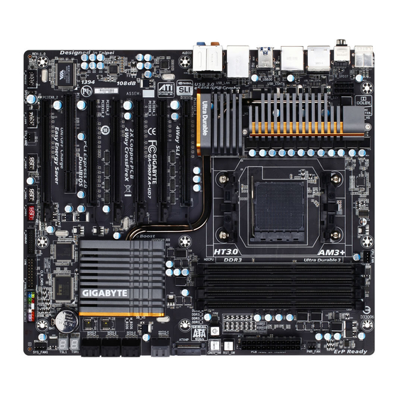
Page 7: Ga-990Fxa-Ud7 Motherboard Layout
GA-990FXA-UD7 Motherboard Layout CPU_FAN KB_MS_USB ATX_12V R_SPDIF Marvell USB_1394_ESATA PWR_FAN 88SE9172 Socket AM3+ USB_ESATA R_USB30 Etron EJ168 USB_LAN RST_SW AMD 990FX PW_SW CMOS_SW AUDIO PCIEX16_1 ATX4P Realtek RTL8111E PCIEX4_1 Marvell GSATA3_7 88SE9172 GSATA3_6 PCIEX8_1 SATA3_4 GA-990FXA-UD7 AMD SB950 PCIEX4_2 SATA3_5... -
Page 8: Ga-990Fxa-Ud7 Motherboard Block Diagram
GA-990FXA-UD7 Motherboard Block Diagram 2 PCI Express x16 4 PCI Express x8 CPU CLK+/- (200 MHz) 2 PCI Express x4 DDR3 2000(O.C.)/1866/1600/1333/1066 MHz AM3+/AM3 CPU Dual Channel Memory Hyper Transport 3.0 PCIe CLK (100 MHz) Switch AMD 990FX PCI Express Bus... -
Page 9: Chapter 1 Hardware Installation
Chapter 1 Hardware Installation Installation Precautions The motherboard contains numerous delicate electronic circuits and components which can become damaged as a result of electrostatic discharge (ESD). Prior to installation, carefully read the user's manual and follow these procedures: • Prior to installation, do not remove or break motherboard S/N (Serial Number) sticker or warranty sticker provided by your dealer. -
Page 10: Product Specifications
Support for DDR3 2000(O.C.)/1866/1600/1333/1066 MHz memory modules Š * To support a DDR3 1866 MHz (and above) memory, you must install an AMD AM3+ CPU first. (Go to GIGABYTE's website for the latest supported memory speeds and memory modules.) Audio Realtek ALC889 codec Š... - Page 11 Storage Interface 2 x eSATA 6Gb/s connectors (including 1 eSATA/USB Combo connector) on the back panel supporting up to 2 SATA 6Gb/s devices Support for RAID 0 and RAID 1 South Bridge: Š Up to 14 USB 2.0/1.1 ports (8 ports on the back panel, including 1 eSATA/ USB Combo connector, 6 ports available through the internal USB headers) 2 x Etron EJ168 chips:...
- Page 12 Support for Microsoft Windows 7/Vista/XP Š ® System Form Factor ATX Form Factor; 30.5cm x 26.3cm Š * GIGABYTE reserves the right to make any changes to the product specifications and product-related information without prior notice. Hardware Installation - 12 -...
-
Page 13: Installing The Cpu And Cpu Cooler
Read the following guidelines before you begin to install the CPU: • Make sure that the motherboard supports the CPU. (Go to GIGABYTE's website for the latest CPU support list.) • Always turn off the computer and unplug the power cord from the power outlet before installing the CPU to prevent hardware damage. - Page 14 B. Follow the steps below to correctly install the CPU into the motherboard CPU socket. • Before installing the CPU, make sure to turn off the computer and unplug the power cord from the power outlet to prevent damage to the CPU. • Do not force the CPU into the CPU socket.
-
Page 15: Installing The Cpu Cooler
1-3-2 Installing the CPU Cooler Follow the steps below to correctly install the CPU cooler on the CPU. (The following procedure uses the GIGABYTE cooler as the example.) Step 1: Step 2: Place the CPU cooler on the CPU. Apply an even and thin layer of thermal grease on the surface of the installed CPU. -
Page 16: Installing The Memory
• Make sure that the motherboard supports the memory. It is recommended that memory of the same capacity, brand, speed, and chips be used. (Go to GIGABYTE's website for the latest supported memory speeds and memory modules.) • Always turn off the computer and unplug the power cord from the power outlet before installing the memory to prevent hardware damage. -
Page 17: Installing A Memory
1-4-2 Installing a Memory Before installing a memory module, make sure to turn off the computer and unplug the power cord from the power outlet to prevent damage to the memory module. DDR3 and DDR2 DIMMs are not compatible to each other or DDR DIMMs. Be sure to install DDR3 DIMMs on this motherboard. -
Page 18: Installing An Expansion Card
Installing an Expansion Card Read the following guidelines before you begin to install an expansion card: • Make sure the motherboard supports the expansion card. Carefully read the manual that came with your expansion card. • Always turn off the computer and unplug the power cord from the power outlet before installing an expansion card to prevent hardware damage. -
Page 19: Setup Of Amd Crossfirex ™ Configuration
Setup of AMD CrossFireX Configuration ™ A. System Requirements - The 2-Way CrossFireX technology currently support Windows 7, Vista, XP operating systems - The 3-Way/4-Way CrossFireX technology currently support Windows 7 and Vista operating systems - A CrossFireX-supported motherboard with two/three/four PCI Express x16 slots and correct driver - Two/three/four CrossFireX-ready graphics cards of identical brand and chip and correct driver ( Current GPUs that support 3-Way/4-Way CrossFireX technology include the ATI Radeon HD 3800, HD 4800, and HD 5800 series and AMD Radeon HD 6950, HD 6970 and HD 6990 series.) -
Page 20: Back Panel Connectors
Back Panel Connectors USB 2.0/1.1 Port The USB port supports the USB 2.0/1.1 specification. Use this port for USB devices such as a USB key- board/mouse, USB printer, USB flash drive and etc. PS/2 Keyboard/Mouse Port Use this port to connect a PS/2 mouse or keyboard. Optical S/PDIF Out Connector This connector provides digital audio out to an external audio system that supports digital optical audio. - Page 21 RJ-45 LAN Port The Gigabit Ethernet LAN port provides Internet connection at up to 1 Gbps data rate. The following escribes the states of the LAN port LEDs. Connection/ Speed LED Activity LED Connection/Speed LED: Activity LED: State Description State Description Orange 1 Gbps data rate...
-
Page 22: Onboard Buttons
Onboard Buttons This motherboard has 3 quick buttons: power button, reset button and clearing CMOS button. The power button and reset button allow users to quickly turn on/off or reset the computer in an open-case environment when they want to change hardware components or conduct hardware testing. Use the clearing CMOS but- ton to clear the CMOS values (e.g. -
Page 23: Internal Connectors
Internal Connectors ATX_12V F_AUDIO SPDIF_O ATX4P F_USB1/F_USB2/F_USB3 CPU_FAN F_USB30 SYS_FAN1/SYS_FAN2 F_1394 PWR_FAN CLR_CMOS SATA3_0/1/2/3/4/5 GSATA3_6/GSATA3_7 F_PANEL Read the following guidelines before connecting external devices: • First make sure your devices are compliant with the connectors you wish to connect. • Before installing the devices, be sure to turn off the devices and your computer. Unplug the power cord from the power outlet to prevent damage to the devices. - Page 24 1/2) ATX_12V/ATX (2x4 12V Power Connector and 2x12 Main Power Connector) With the use of the power connector, the power supply can supply enough stable power to all the com- ponents on the motherboard. Before connecting the power connector, first make sure the power supply is turned off and all devices are properly installed.
- Page 25 3) ATX4P (PCIe Power Connector) The power connector provides auxiliary power to the onboard PCI Express x16 slots. When two or more graphics cards are to be installed, we recommend that you connect the SATA power cable from the power supply to the ATX4P connector to ensure system stability. 1 2 3 Pin No.
- Page 26 7) SATA3_0/1/2/3/4/5 (SATA 6Gb/s Connectors, Controlled by AMD SB950 South Bridge) The SATA connectors conform to SATA 6Gb/s standard and are compatible with SATA 3Gb/s and SATA 1.5Gb/s standards. Each SATA connector supports a single SATA device. The AMD SB950 South Bridge supports RAID 0, RAID 1, RAID 5, RAID 10, and JBOD.
-
Page 27: F_Panel Front Panel Header
9) F_PANEL (Front Panel Header) Connect the power switch, reset switch, speaker, chassis intrusion switch/sensor and system status indicator on the chassis to this header according to the pin assignments below. Note the positive and negative pins before connecting the cables. Message/Power/ Power Speaker... - Page 28 10) F_AUDIO (Front Panel Audio Header) The front panel audio header supports Intel High Definition audio (HD) and AC'97 audio. You may connect your chassis front panel audio module to this header. Make sure the wire assignments of the module con- nector match the pin assignments of the motherboard header.
-
Page 29: Usb 2.0/1.1 Headers
12) F_USB1/F_USB2/F_USB3 (USB 2.0/1.1 Headers) The headers conform to USB 2.0/1.1 specification. Each USB header can provide two USB ports via an optional USB bracket. For purchasing the optional USB bracket, please contact the local dealer. Pin No. Definition Power (5V) Power (5V) USB DX- USB DY-... -
Page 30: Clear Cmos Jumper
14) F_1394 (IEEE 1394a Header) The header conforms to IEEE 1394a specification. The IEEE 1394a header can provide one IEEE 1394a port via an optional IEEE 1394a bracket. For purchasing the optional IEEE 1394a bracket, please con- tact the local dealer. Pin No. - Page 31 16) BAT (Battery) The battery provides power to keep the values (such as BIOS configurations, date, and time information) in the CMOS when the computer is turned off. Replace the battery when the battery voltage drops to a low level, or the CMOS values may not be accurate or may be lost. You may clear the CMOS values by removing the battery: 1.
- Page 32 Hardware Installation - 32 -...
-
Page 33: Chapter 2 Bios Setup
To see more advanced BIOS Setup menu options, you can press <Ctrl> + <F1> in the main menu of the BIOS Setup program. To upgrade the BIOS, use either the GIGABYTE Q-Flash or @BIOS utility. Q-Flash allows the user to quickly and easily upgrade or back up BIOS without entering the operating •... -
Page 34: Startup Screen
A. The LOGO Screen (Default) Function Keys B. The POST Screen Award Modular BIOS v6.00PG Copyright (C) 1984-2011, Award Software, Inc. GA-990FXA-UD7 F1a Motherboard Model BIOS Version Function Keys <DEL>: BIOS Setup <F9>: XpressRecovery2 <F12>: Boot Menu <End>: Qflash 04/22/2011-RD990-SB950-7A66FG01C-00 Function Keys: <TAB>: POST SCREEN... -
Page 35: The Main Menu
The Main Menu Once you enter the BIOS Setup program, the Main Menu (as shown below) appears on the screen. Use ar- row keys to move among the items and press <Enter> to accept or enter a sub-menu. (Sample BIOS Version: F1a) CMOS Setup Utility-Copyright (C) 1984-2011 Award Software MB Intelligent Tweaker(M.I.T.) Load Fail-Safe Defaults... - Page 36 The Functions of the <F11> and <F12> keys (For the Main Menu Only) F11: Save CMOS to BIOS This function allows you to save the current BIOS settings to a profile. You can create up to 8 profiles (Profile 1-8) and name each profile.
-
Page 37: Mb Intelligent Tweaker(M.i.t.)
MB Intelligent Tweaker(M.I.T.) CMOS Setup Utility-Copyright (C) 1984-2011 Award Software MB Intelligent Tweaker(M.I.T.) Item Help CPU Clock Ratio [Auto] Menu Level CPU NorthBridge Freq. [Auto] Core Performance Boost [Enabled] (Note) CPB Ratio (Note) [Auto] Turbo CPB [Disabled] (Note) CPU Host Clock Control [Auto] x CPU Frequency(MHz) PCIE Clock(MHz) - Page 38 CPU Clock Ratio Allows you to alter the clock ratio for the installed CPU. The adjustable range is dependent on the CPU being used. CPU NorthBridge Freq. Allows you to alter the North Bridge controller frequency for the installed CPU. The adjustable range is dependent on the CPU being used.
-
Page 39: Dram Configuration
DRAM Configuration CMOS Setup Utility-Copyright (C) 1984-2011 Award Software DRAM Configuration Item Help CPU Host Clock Control [Auto] Menu Level x CPU Frequency(MHz) Set Memory Clock [Auto] x Memory Clock x6.66 1333Mhz DCTs Mode [Unganged] DDR3 Timing Items [Auto] Auto x 1T/2T Command Timing Auto x CAS# latency Auto... - Page 40 CPU Host Clock Control, CPU Frequency (MHz), Set Memory Clock, Memory Clock The settings under the four items above are synchronous to those under the same items on the MB In- telligent Tweaker(M.I.T.) main menu. DCTs Mode Allows you to set memory control mode. Ganged Sets memory control mode to single dual-channel.
- Page 41 Data Drive Strength Options are: Auto (default), 0.75x, 1.0x, 1.25x, 1.5x. MEMCLK Drive Strength Options are: Auto (default), 0.75x, 1.0x, 1.25x, 1.5x. Addr/Cmd Drive Strength Options are: Auto (default), 1.0x, 1.25x, 1.5x, 2.0x. CS/ODT Drive Strength Options are: Auto (default), 1.0x, 1.25x, 1.5x, 2.0x. CKE Drive Strength Options are: Auto (default), 1.0x, 1.25x, 1.5x, 2.0x.
- Page 42 ******** System Voltage Optimized ******** System Voltage Control Determines whether to manually set the system voltages. Auto lets the BIOS automatically set the system voltages as required. Manual allows all voltage control items below to be configurable. (Default: Auto) CPU PLL Voltage Control Allows you to set the CPU PLL voltage.
-
Page 43: Standard Cmos Features
Standard CMOS Features CMOS Setup Utility-Copyright (C) 1984-2011 Award Software Standard CMOS Features Item Help Date (mm:dd:yy) Wed, Mar 16 2011 Menu Level Time (hh:mm:ss) 22:31:24 IDE Channel 0 Master [None] IDE Channel 0 Slave [None] IDE Channel 1 Master [None] ... - Page 44 Halt On Allows you to determine whether the system will stop for an error during the POST. All Errors Whenever the BIOS detects a non-fatal error the system boot will stop. No Errors The system boot will not stop for any error. All, But Keyboard The system boot will not stop for a keyboard error but stop for all other errors.
-
Page 45: Advanced Bios Features
Advanced BIOS Features CMOS Setup Utility-Copyright (C) 1984-2011 Award Software Advanced BIOS Features Item Help AMD C1E Support [Auto] Menu Level Virtualization [Disabled] AMD K8 Cool&Quiet control [Auto] CPU Unlock (Note) [Disabled] CPU core Control [Auto] x CPU core 0 Enabled x CPU core 1 Enabled... - Page 46 Virtualization Virtualization allows a platform to run multiple operating systems and applications in independent parti- tions. With virtualization, one computer system can function as multiple virtual systems. (Default: Disabled) AMD K8 Cool&Quiet control Auto Lets the AMD Cool'n'Quiet driver dynamically adjust the CPU clock and VID to re- duce heat output from your computer and its power consumption.
- Page 47 (Default: Disabled) Full Screen LOGO Show Allows you to determine whether to display the GIGABYTE Logo at system startup. Disabled displays normal POST message. (Default: Enabled) IOMMU support Enables or disables AMD IOMMU support.
-
Page 48: Integrated Peripherals
Integrated Peripherals CMOS Setup Utility-Copyright (C) 1984-2011 Award Software Integrated Peripherals Item Help OnChip SATA Controller [Enabled] Menu Level OnChip SATA Type [Native IDE] x OnChip SATA Port4/5 Type x OnChip SATA RAID5 Support Enabled OnChip SATA3.0 Support [Enabled] x OnChip SATA Port as ESP Press Enter F_USB30 Controller [Enabled]... - Page 49 OnChip SATA Port as ESP CMOS Setup Utility-Copyright (C) 1984-2011 Award Software OnChip SATA Port as ESP Item Help Port0 as ESP [Disabled] Menu Level Port1 as ESP [Disabled] Port2 as ESP [Disabled] Port3 as ESP [Disabled] Port4 as ESP [Disabled] Port5 as ESP [Disabled]...
- Page 50 GSATA3 Ctrl Mode (Marvell 88SE9172 chip, GSATA3_6/7 connector) Enables or disables RAID for the SATA controller integrated in the Marvell 88SE9172 chip or configures the SATA controller to AHCI mode. Disables RAID for the SATA controller and configures the SATA controller to IDE mode.
- Page 51 SMART LAN (LAN Cable Diagnostic Function) CMOS Setup Utility-Copyright (C) 1984-2011 Award Software SMART LAN Item Help Start detecting at Port..Menu Level Part1-2 Status = Open / Length = Part3-6 Status = Open / Length = Part4-5 Status = Open / Length = Part7-8 Status = Open / Length = higf: Move Enter: Select...
- Page 52 BIOS Setup - 52 -...
-
Page 53: Power Management Setup
Power Management Setup CMOS Setup Utility-Copyright (C) 1984-2011 Award Software Power Management Setup Item Help ACPI Suspend Type [S3(STR)] Menu Level Soft-Off by Power button [Instant-off] USB Wake Up from S3 [Enabled] Modem Ring Resume [Disabled] PME Event Wake Up [Enabled] HPET Support [Enabled]... - Page 54 PME Event Wake Up Allows the system to be awakened from an ACPI sleep state by a wake-up signal from a PCI or PCIe de- vice. Note: To use this function, you need an ATX power supply providing at least 1A on the +5VSB lead. (Default: Enabled) HPET Support (Note)
-
Page 55: Pc Health Status
PC Health Status CMOS Setup Utility-Copyright (C) 1984-2011 Award Software PC Health Status Item Help Hardware Thermal Control [Enabled] Menu Level Reset Case Open Status [Disabled] Case Opened Vcore 1.364V DDR3 1.5V 1.536V +3.3V 3.280V +12V 12.048V Current System Temperature Current CPU Temperature Current CPU FAN Speed 1962 RPM... - Page 56 Current Voltage(V) Vcore/DDR3 1.5V/+3.3V/+12V Displays the current system voltages. Current System/CPU Temperature Displays current system/CPU temperature. Current CPU/SYSTEM/POWER FAN Speed (RPM) Displays current CPU/system/power fan speed. CPU Warning Temperature Sets the warning threshold for CPU temperature. When CPU temperature exceeds the threshold, BIOS will emit warning sound.
-
Page 57: Load Fail-Safe Defaults
Load Fail-Safe Defaults CMOS Setup Utility-Copyright (C) 1984-2011 Award Software MB Intelligent Tweaker(M.I.T.) Load Fail-Safe Defaults Standard CMOS Features Load Optimized Defaults Advanced BIOS Features Set Supervisor Password Integrated Peripherals Set User Password Power Management Setup Save &... -
Page 58: Set Supervisor/User Password
2-11 Set Supervisor/User Password CMOS Setup Utility-Copyright (C) 1984-2011 Award Software MB Intelligent Tweaker(M.I.T.) Load Fail-Safe Defaults Standard CMOS Features Load Optimized Defaults Advanced BIOS Features Set Supervisor Password Integrated Peripherals Set User Password Power Management Setup Save &... -
Page 59: Save & Exit Setup
2-12 Save & Exit Setup CMOS Setup Utility-Copyright (C) 1984-2011 Award Software MB Intelligent Tweaker(M.I.T.) Load Fail-Safe Defaults Standard CMOS Features Load Optimized Defaults Save to CMOS and EXIT (Y/N)? Y Advanced BIOS Features Set Supervisor Password Integrated Peripherals Set User Password ... - Page 60 BIOS Setup - 60 -...
-
Page 61: Chapter 3 Drivers Installation
• After "Xpress Install" installs all of the drivers, a dialog box will appear asking whether to install new GIGABYTE utilities. Click Yes to automatically install the utilities. Or click No if you want to manually select the utilities to install on the Application Software page later. -
Page 62: Application Software
Application Software This page displays all the utilities and applications that GIGABYTE develops and some free software. You can click the Install button on the right of an item to install it. Technical Manuals This page provides GIGABYTE's application guides, content descriptions for this driver disk, and the mother- board manuals. -
Page 63: Contact
Contact For the detailed contact information of the GIGABYTE Taiwan headquarter or worldwide branch offices, click the URL on this page to link to the GIGABYTE website. System This page provides the basic system information. - 63 - Drivers Installation... -
Page 64: Download Center
The latest version of the BIOS, drivers, or applications will be displayed. New Utilities This page provides a quick link to GIGABYTE's lately developed utilities for users to install. You can click the Install button on the right of an item to install it. -
Page 65: Chapter 4 Unique Features
Chapter 4 Unique Features Xpress Recovery2 Xpress Recovery2 is a utility that allows you to quickly compress and back up your system data and perform restoration of it. Supporting NTFS, FAT32, and FAT16 file systems, Xpress Recovery2 can back up data on PATA and SATA hard drives and restore it. - Page 66 Step 3: Step 4: When partitioning your hard drive, make sure to After the operating system is installed, click Start, leave unallocated space (10 GB or more is recom- right-click the Computer and select Manage. Go to mended; actual size requirements vary, depending Disk Management to check disk allocation.
- Page 67 D. Using the Restore Function in Xpress Recovery2 Select RESTORE to restore the backup to your hard drive in case the system breaks down. The RESTORE option will not be present if no backup is created before. E. Removing the Backup Step 1: Step 2: If you wish to remove the backup file, select...
-
Page 68: Bios Update Utilities
4-2-1 Updating the BIOS with the Q-Flash Utility A. Before You Begin From GIGABYTE's website, download the latest compressed BIOS update file that matches your moth- erboard model. Extract the file and save the new BIOS file (e.g. 99FXAUD7.F1) to your USB flash drive, or hard drive. - Page 69 B. Updating the BIOS When updating the BIOS, choose the location where the BIOS file is saved. The following procedure as- sumes that you save the BIOS file to a USB flash drive. Step 1: Insert the USB flash drive containing the BIOS file into the computer. In the main menu of Q-Flash, use the up or down arrow key to select Update BIOS from Drive and press <Enter>.
- Page 70 Step 4: Press <Esc> and then <Enter> to exit Q-Flash and reboot the system. As the system boots, you should see the new BIOS version is present on the POST screen. Step 5: During the POST, press <Delete> to enter BIOS Setup. Select Load Optimized Defaults and press <Enter> to load BIOS defaults.
-
Page 71: Updating The Bios With The @Bios Utility
BIOS or a system that is unable to start. Do not use the G.O.M. (GIGABYTE Online Management) function when using @BIOS. GIGABYTE product warranty does not cover any BIOS damage or system failure resulting from an inad- equate BIOS flashing. -
Page 72: Easytune 6
EasyTune 6 GIGABYTE's EasyTune 6 is a simple and easy-to-use interface that allows users to fine-tune their system settings or do overclock/overvoltage in Windows environment. The user-friendly EasyTune 6 interface also includes tabbed pages for CPU and memory information, letting users read their system-related information without the need to install additional software. -
Page 73: Easy Energy Saver
The Easy Energy Saver Interface A. Meter Mode In Meter Mode, GIGABYTE Easy Energy Saver shows how much power they have saved in a set period of time. Meter Mode - Button Information Table Button Description... - Page 74 B. Total Mode In Total Mode, users are able to see how much total power savings they have accumulated in a set period of time since activating Easy Energy Saver for the first time (Note 3) Total Mode - Button Information Table Button Description Easy Energy Saver On/Off Switch (Default: Off) Dynamic CPU Frequency Function On/Off Switch (Default: Off)
-
Page 75: Q-Share
Q-Share, you are able to share your data with computers on the same network, making full use of Internet resources. Directions for using Q-Share After installing Q-Share from the motherboard driver disk, go to Start>All Programs>GIGABYTE>Q-Share. exe to launch the Q-Share tool. Find the Q-Share icon in the notification area and right-click on this icon to configure the data sharing settings. -
Page 76: Smart Recovery
SMART Recovery With SMART Recovery, users can quickly create backups of changed data files or copy files from a spe- (Note 1) cific backup on PATA and SATA hard drives (partitioned on NTFS file system) in Windows 7/Vista. Instructions: In the main menu, click the Config button to open the Smart Recov- ery Preference dialog box. -
Page 77: Auto Green
Auto Green Auto Green is an easy-to-use tool that provides users with simple options to enable system power savings via a Bluetooth cell phone. When the phone is out of the range of the computer's Bluetooth receiver, the sys- tem will enter the specified power saving mode. The Configuration dialog box: First, you have to set your Bluetooth cell phone as a portable key. -
Page 78: Cloud Oc
Cloud OC Cloud OC is an easy-to-use overclocking utility designed for system overclock- (Note 1) ing via virtually any Internet-connected device, such as a smart phone, iPhone, note- book PC, etc. By simply connecting to an Internet browser via LAN, wireless LAN, or Bluetooth and logging in to the Cloud OC server, you can easily access three major functions of Cloud (Note 2) -
Page 79: Chapter 5 Appendix
Chapter 5 Appendix Configuring SATA Hard Drive(s) To configure SATA hard drive(s), follow the steps below: A. Install SATA hard drive(s) in your computer. B. Configure SATA controller mode in BIOS Setup. C. Configure a RAID array in RAID BIOS. (Note 1) D. - Page 80 B. Configuring SATA controller mode in BIOS Setup Make sure to configure the SATA controller mode correctly in system BIOS Setup. Step 1: Turn on your computer and press <Delete> to enter BIOS Setup during the POST (Power-On Self-Test). Make sure OnChip SATA Controller is enabled. To enable RAID for the SATA3_0/1/2/3 connectors, set On- Chip SATA Type to RAID.
- Page 81 C. Configuring RAID set in RAID BIOS Enter the RAID BIOS setup utility to configure a RAID array. Skip this step and proceed with the installation of Windows operating system for a non-RAID configuration. Step 1: After the POST memory test begins and before the operating system boot begins, look for a message which says "Press <Ctrl-F>...
- Page 82 Option ROM Utility (c) 2011 Advanced Micro Devices, Inc. [ LD Define Menu ] LD No LD Name RAID Mode LD 1 Logical Drive 1 RAID 0 Stripe Block 64 KB Initialization Gigabyte Boundary Read Policy Read Ahead Write Policy WriteBack [ Drives Assignments ] Port:ID Drive Model Capabilities Capacity (GB) Assignment...
- Page 83 In the following procedure, we'll create RAID 0 as an example. 1. Under the RAID Mode section, press the <SPACE> key to select RAID 0. 2. Set the Stripe Block size. 64 KB is the default. 3. Under the Drives Assignments section, press the up or down arrow key to highlight a drive. 4.
- Page 84 View Drive Assignments The View Drive Assignments option in the Main Menu displays whether the attached hard drives are as- signed to a disk array or are unassigned. Under the Assignment column, drives are labeled with their as- signed disk array or shown as Free if unassigned. Option ROM Utility (c) 2011 Advanced Micro Devices, Inc.
-
Page 85: Configuring Marvell 88Se9172 Sata Controllers
5-1-2 Configuring Marvell 88SE9172 SATA Controllers A. Installing SATA hard drive(s) in your computer Attach one end of the SATA signal cable to the rear of the SATA hard drive and the other end to avail- able SATA port on the motherboard. One of the Marvell 88SE9172 SATA controllers controls the onboard GSATA3_6/7 connector and the other controls the eSATA ports on the back panel. - Page 86 C. Configuring a RAID array in RAID BIOS Enter the RAID BIOS setup utility to configure a RAID array. Skip this step and proceed to the installation of Windows operating system for a non-RAID configuration. After the POST memory test begins and before the operating system boot begins, look for a message which says "Press <Ctrl>+<M>...
- Page 87 Create a RAID Array: Step 1: On the main screen, press <Enter> on the RAID tab. Then the RAID Config menu appears (Figure 4). Press <Enter> on the Create VD item. Marvell BIOS Setup (c) 2009 Marvell Technology Group Ltd. [ Selection] [ Adapter] [ Devices]...
- Page 88 Step 3: On the Create VD menu (Figure 6), use the up or down arrow key to move the selection bar to select an item and press <Enter> to display options. Set the required items in sequence and press the down arrow key to proceed to the next item.
- Page 89 When completed, the RAID tab will display the new array. (Figure 8) Marvell BIOS Setup (c) 2009 Marvell Technology Group Ltd. [ Selection] [ Adapter] [ Devices] [ RAID ] [Virtual Disks] Name Size Level Status Stripe CacheMode 152.4GB RAID0 ONLINE 64KB WriteBack...
- Page 90 Use the Marvell Storage Utility in the Operating System: With the Marvell Storage utility, you can set up an array or view the current array status in the operating system. To install the utility, insert the motherboard driver disk, then go to Application Software\Install Ap- plication Software and select Marvell Storage Utility to install.
-
Page 91: Installing The Sata Raid/Ahci Driver And Operating System
5-1-3 Installing the SATA RAID/AHCI Driver and Operating System With the correct BIOS settings, you are ready to install Windows 7/Vista/XP. A. Installing Windows 7/Vista (The following instructions use Windows 7 as the example operating system.) Step 1: Boot from the Windows 7/Vista setup disk and perform standard OS installation steps. When you arrive at the "Where do you want to install Windows?"... - Page 92 Step 2: For the Marvell 88SE9172: Insert the motherboard driver disk and then browse to the location of the driver. The locations of the drivers are as follows: RAID driver for Windows 32-bit: \BootDrv\Marvell\RAID\i386 RAID driver for Windows 64-bit: \BootDrv\Marvell\RAID\amd64 AHCI driver for Windows 32-bit: \BootDrv\Marvell\AHCI\Floppy32 AHCI driver for Windows 64-bit: \BootDrv\Marvell\AHCI\Floppy64 Step 3:...
- Page 93 B. Installing Windows XP Before installing Windows XP, connect a USB floppy disk drive to your computer first because you need to in- stall the SATA RAID/AHCI driver from a floppy disk that contains the driver during the OS installation. Without the driver, the hard drive(s) may not be recognized during the Windows setup process.
- Page 94 Refer to the following for installing the driver during the Windows setup process. Step 1: Restart your system to boot from the Windows XP setup disk and press <F6> as soon as you see the mes- sage "Press F6 if you need to install a 3rd party SCSI or RAID driver." A screen will then appear asking you to specify an additional SCSI adapter.
- Page 95 For the Marvell 88SE9172: Insert the floppy disk containing the SATA RAID/AHCI driver and press <Enter>. Select either the 32-bit or 64-bit items depending on whether you want to install the 32-bit or 64-bit version of Windows XP (Figure 5). Both of the Marvell shared library and Marvell 91xx SATA RAID Controller need to be installed.
- Page 96 Rebuilding an Array: Rebuilding is the process of restoring data to a hard drive from other drives in the array. Rebuilding applies only to fault-tolerant arrays such as RAID 1, RAID 5, or RAID 10. To replace the old drive, make sure to use a new drive of equal or greater capacity.
- Page 97 For the Marvell 88SE9172: Turn off your computer and replace the failed hard drive with a new one. Restart your computer. To enable an automatic rebuild in the operating system, you have to set the new hard drive as a Spare drive in the RAID setup utility first.
- Page 98 Step 3: Make sure you have installed the Marvell RAID driver and Marvell Storage Utility from the motherboard driver disk. While in the operating system, launch the Marvell Storage Utility from Start\All Programs\Marvell Storage Utility\Marvell Tray, right-click on the icon in the notification area, and select Open MSU. Then login the Marvell Storage Utility.
-
Page 99: Configuring Audio Input And Output
Configuring Audio Input and Output 5-2-1 Configuring 2/4/5.1/7.1-Channel Audio The motherboard provides six audio jacks on the back panel which support 2/4/5.1/7.1-channel audio. (Note) The picture to the right shows the default audio jack Center/Subwoofer Line In Speaker Out assignments. Rear Speaker Out Front Speaker Out The integrated HD (High Definition) audio provides... - Page 100 Step 2: Connect an audio device to an audio jack. The The cur- rent connected device is dialog box appears. Select the device according to the type of device you connect. Then click OK. Step 3: On the Speakers screen, click the Speaker Configura- tion tab.
-
Page 101: Configuring S/Pdif Out
5-2-2 Configuring S/PDIF Out The S/PDIF Out jacks can transmit audio signals to an external decoder for decoding to get the best audio quality. 1. Connecting a S/PDIF Out Cable: Connect a S/PDIF coaxial cable or a S/PDIF optical cable (either one) to the corresponding S/PDIF out con- nector as shown below and an external decoder for transmitting the S/PDIF digital audio signals. -
Page 102: Enabling The Dolby Home Theater Function
5-2-3 Enabling the Dolby Home Theater Function Before Dolby Home Theater is enabled, you get only 2-channel playback output (from the front speakers) when playing 2-channel stereo sources. You must play 4-, 5.1-, or 7.1- chan- nel content to get 4-, 5.1-, or 7.1- channel audio effects. With Dolby Home Theater enabled, 2-channel stereo content will be transformed into multi-channel audio, creating a virtual sur- round sound environment. -
Page 103: Configuring Microphone Recording
5-2-4 Configuring Microphone Recording Step 1: After installing the audio driver, the HD Audio Manager icon will appear in the notification area. Double-click the icon to access the HD Audio Manager. Step 2: Connect your microphone to the Mic in jack (pink) on the back panel or the Mic in jack (pink) on the front panel. - Page 104 Step 5: After completing the settings above, click Start, point to All Programs, point to Accessories, and then click Sound Recorder to begin the sound recording. * Enabling Stereo Mix If the HD Audio Manager does not display the recording device you wish to use, refer to the steps below. The following steps explain how to enable Stereo Mix (which may be needed when you want to record sound from your computer).
-
Page 105: Using The Sound Recorder
Step 4: Now you can access the HD Audio Manager to config- ure Stereo Mix and use Sound Recorder to record the sound. 5-2-5 Using the Sound Recorder A. Recording Sound 1. Make sure you have connected the sound input device (e.g. microphone) to the computer. 2. -
Page 106: Troubleshooting
Troubleshooting 5-3-1 Frequently Asked Questions To read more FAQs for your motherboard, please go to the Support & Downloads\FAQ page on GIGABYTE's website. Q: In the BIOS Setup program, why are some BIOS options missing? A: Some advanced options are hidden in the BIOS Setup program. Press <Delete> to enter BIOS Setup during the POST. In the Main Menu, press <Ctrl>+<F1>... -
Page 107: Troubleshooting Procedure
5-3-2 Troubleshooting Procedure If you encounter any troubles during system startup, follow the troubleshooting procedure below to solve the problem. START Turn off the power. Remove all peripherals, connecting cables, and power cord etc. Make sure the motherboard does not short-circuit with the chassis or Isolate the short circuit. - Page 108 The power supply, CPU or When the computer is turned on, is the CPU cooler running? CPU socket might fail. The problem is verified and solved. The graphics card, expansion slot, or monitor Check if there is display on your monitor. might fail.
-
Page 109: Post Error Code
POST Error Code POST (hex) Description Test CMOS R/W functionality Early chipset initialization: -Disable shadow RAM - Program basic chipset registers Detect memory - Auto-detection of DRAM size, type and ECC Expand compressed BIOS code to DRAM Call chipset hook to copy BIOS back to E000 & F000 shadow RAM Expand the Xgroup codes locating in physical address 1000:0 DualBIOS init (optional) Initial Superio_Early_Init switch... - Page 110 POST (hex) Description Prepare BIOS resource map for PCI & PnP use. If ESCD is valid, take into consider- ation of the ESCD's legacy information Early PCI initialization: - Enumerate PCI bus number - Assign memory & I/O resource - Search for a valid VGA device & VGA BIOS, and put it into C000:0 1.
- Page 111 POST (hex) Description Initialize the combined Trend Anti-Virus code 1. Initialize Init_Onboard_Super_IO 2. Initialize Init_Onbaord_AUDIO Okay to enter Setup utility; i.e. not until this POST stage can users enter the CMOS setup utility Reset keyboard is Early_Reset_KB is not defined Initialize PS/2 Mouse Prepare memory size information for function call: INT 15h ax=E820h Turn on L2 cache...
- Page 112 POST (hex) Description 1. Enable L2 cache 2. Program daylight saving 3. Program boot up speed 4. Chipset final initialization 5. Power management final initialization 6. Clear screen & display summary table 7. Boot BIOS support (popup menu) Update keyboard LED & typematic rate 1.
- Page 113 - 113 - Appendix...
- Page 114 Appendix - 114 -...
- Page 115 Web address: http://latam.giga-byte.com TEL: +86-24-83992901 • Giga-Byte SINGAPORE PTE. LTD. - Singapore FAX: +86-24-83992909 WEB address : http://www.gigabyte.sg • GIGABYTE TECHNOLOGY (INDIA) LIMITED - India • Thailand WEB address : http://www.gigabyte.in WEB address : http://th.giga-byte.com • Saudi Arabia • Vietnam WEB address : http://www.gigabyte.com.sa...
- Page 116 WEB address : http://www.gigabyte.com.gr WEB address : http://www.gigabyte.kz • Czech Republic You may go to the GIGABYTE website, select your language WEB address : http://www.gigabyte.cz in the language list on the top right corner of the website. • GIGABYTE Global Service System...
Need help?
Do you have a question about the GA-990FXA-UD7 and is the answer not in the manual?
Questions and answers