Sign In
Upload
Download
Table of Contents
Contents
Add to my manuals
Delete from my manuals
Share
URL of this page:
HTML Link:
Bookmark this page
Add
Manual will be automatically added to "My Manuals"
Print this page
×
Bookmark added
×
Added to my manuals
Manuals
Brands
Hydac Manuals
Test Equipment
CTU 15 Series
Operating and maintenance instructions manual
Hydac CTU 15 Series Operating And Maintenance Instructions Manual
Contaminationtest unit
Hide thumbs
1
2
3
4
5
6
7
8
9
10
11
12
13
14
15
16
17
18
19
20
21
22
23
24
25
26
27
28
29
30
31
32
33
34
35
36
37
38
39
40
41
42
43
44
45
46
47
48
49
50
51
52
53
54
55
56
57
58
59
60
61
62
63
64
65
66
67
68
69
70
71
72
73
74
75
76
77
78
79
80
81
82
83
84
85
86
87
88
89
90
91
92
93
94
95
96
97
98
99
100
101
102
103
104
105
106
107
108
109
110
111
112
113
114
115
116
117
118
119
120
page
of
120
Go
/
120
Contents
Table of Contents
Bookmarks
Table of Contents
Table of Contents
General
Target Group of the Manual
Tab. 1 Target Group
Illustrations in the Manual
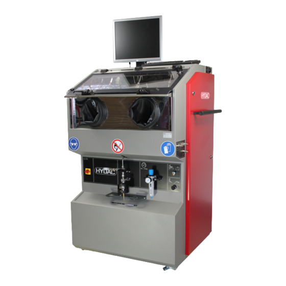
Illustration on the Title Page
Fig. 1 Overview / Labeling of the Title Page
Representation of Intermediate Results/Results
Representation of Procedural Instructions
Representation of Requirements
Supplementary Symbols
Representation of Warning / General Safety Information
Signal Words and Their Meaning in the General Safety Information
Exclusion of Liability / Warranty
Notes on Copyright
Safety
Target Group / Required Personnel Qualification
Tab. 2 Target Group / Required Personnel Qualification
Hazard Symbols / Pictograms
Danger Notifications
Safety Marking
Fig. 2 Placement of Safety Symbols/Pictograms
Observing Regulatory Information
Observing Environmental Precautions
Wear Personal Protection Equipment
Fig. 3 Minimum Distance for Fire Fighting
Fire-Fighting Measures
Shutdown in an Emergency (EMERGENCY STOP)
Product and Technical Specifications
Checking the Scope of Delivery
Tab. 3 Scope of Delivery
Intended Use
Improper Use or Use Deviating from Intended Use
Technical Data
Tab. 4 Technical Data - CTU
Tab. 5 Technical Data - Ultrasound Facility (Optional)
Decoding the Name Plate
Fig. 4 Decoding the Name Plate
Model Code
Fig. 5 Model Code
Dimensions
Fig. 6 Dimensions of the Extraction Unit
Fig. 7 Dimensions of the Extraction Chamber
Components/Operating Elements
Fig. 8 Components/Operating Elements (Example: Ctu125X)
Fig. 9 Ports in the Extraction Chamber
Ports in the Extraction Chamber
Control Panel
Fig. 10 Control Panel
Transporting / Storing the Extraction Unit
Transporting with a Fork Lift Truck
Fig. 11 Moving the Extraction Unit
Fig. 12 Transport the Extraction Unit with a Fork Lift Truck. Example Illustration CTU 105X
Fig. 13 Packaging the Extraction Unit
Fig. 14 Moving Using the Handle
Setting up the Extraction Unit
Setting Up/Assembling/Commissioning
Making the Electrical Connections
Mounting/Connecting the Monitor and Keyboard
Fig. 15 Connecting the Components
Ultrasound Unit / Mounting/Connecting the Vibrator (Optional)
Suctioning the Machine Room
Fig. 16 Connecting the Ultrasonic Unit/Vibrator
Fig. 17 Suctioning the Machine Compartment
Suctioning of Devices and Extraction Chamber
Connecting an Air Extractor
Fig. 18 Suctioning the Extraction Chamber
Connecting the Compressed Air Connection
Connecting the Foot Switch
Fig. 19 Connecting the Foot Switch
Commissioning
Operation
Switching the Extraction Unit on / off
Fig. 20 Opening/Closing the Door
Opening/Closing the Door
Fig. 21 Pen (A)
Selecting the Operating Modes
Performing the Spray Extraction
Fig. 22 Extraction Chamber with Grating
Fig. 23 Extraction Chamber with Basket Mount
Performing Air Extraction
Running Flushing of Inner Chamber
Fig. 24 Flushing the Interior of the Extraction Chamber
Preparing for Ultrasonic Extraction
Fig. 25 Ultrasonic Converter on the Extraction Chamber
Fig. 26 Extraction Chamber with Mounts
Performing Ultrasonic Extraction
Determining the Negative Control Value - Settings/Parameters
Tab. 6 Achievable Negative Control Value
Tab. 7 Effort to Achieve the Negative Control Value
Creating Cascades
Cascading the Filter Membranes / Changing the Filter Membranes
Tab. 8 Cascading the Filter Membrane Holder
Fig. 27 Cascading the Filter Membrane Holder
Operating the Filter Membrane Holder
Labeling the Filter Membrane
Tab. 9 Example - Labeling the Filter Membrane
Overview of the Variants / Options
Variant a (Add Flushing)
Fig. 28 Variant a - Add Flushing
Variante -EA (Extraction Air)
Fig. 29 Variant -EA
Option - Connecting External Flushing Ports
Fig. 30 Connecting External Flushing Ports
Eliminating Errors
Tab. 10 Eliminating Errors
Carrying out the Maintenance / Inspection
Maintenance Table
Cleaning the Extraction Chamber in the Case of a Solvent Cleaner as Test Liquid
Cleaning the Door
Cleaning the Extraction Chamber in the Case of a Test Liquid of Water with Surfac- Tants
Cleaning the Extraction Chamber
Maintaining an Electrostatically Charged Door
Dismounting / Installing the Side Cover
Changing the Test Fluid
Draining the Test Liquid / Emptying the Extraction Unit
Filling the Test Liquid / Filling the Extraction Unit
Tab. 11 Volume Calculation
Checking the Hoses
Replacing Hoses/Plastic Pipe
Checking the Screwed and Plug Connections
Visual Inspection of the Electric Components/Cables
Avoiding the Mixing of Test Liquids - Flushing the Extraction Unit
Cleaning the Diffuser on the Filter Membrane Holder
Fig. 31 Cleaning the Diffuser
Checking the Calibration of the Flow Meter
Checking the Protective Gloves
Preparing for Changing the Filter Element
Changing the Filter Element - MRF1 E
Replacing the Pen with the Hose
Checking that the Pen Is Earthed
Decommissioning / Disposal
Temporary Shutdown
Permanent Shutdown
Disposal / Recycling
Finding Spare Parts / Accessories
Tab. 13 Spare Parts List
Tab. 14 Spare Parts for the Filter Membrane Holder Ø 47 MM, All
Tab. 15 Spare Parts for the Filter Membrane Holder Ø 47 MM, CTMH
Tab. 16 Spare Parts List for Safety-Related Components
Finding Accessories
Tab. 17 Accessories List for Water with Surfactants as Test Liquid
Tab. 18 Accessories List for Water with Surfactants or Solvent Cleaners as Test Liquid
Contacting Customer Service
Tab. 19 HYDAC Service Germany
EC Declaration of Conformity
Table of Illustrations
Glossary
Index
Advertisement
Quick Links
Download this manual
CTU 1x5x
ContaminationTest Unit
Operating and Maintenance Instructions
English (translation of original instructions)
Document No. : 4603539
Follow these instructions for proper and safe use.
Keep for future reference.
Table of
Contents
Previous
Page
Next
Page
1
2
3
4
5
Advertisement
Chapters
Table of Contents
3
Table of Illustrations
109
Table of Contents
Need help?
Do you have a question about the CTU 15 Series and is the answer not in the manual?
Ask a question
Questions and answers
Related Manuals for Hydac CTU 15 Series
Test Equipment Hydac CTU 2 Series Operating And Maintenance Instructions Manual
Contamination test unit (108 pages)
Test Equipment Hydac CTU 1000 Series Operating And Maintenance Instructions Manual
Contamination test unit (92 pages)
Test Equipment Hydac CTU 1000 Operating And Maintenance Instructions Manual
Contaminationtest unit (120 pages)
Test Equipment Hydac CTU 1 5 Series Operating Instructions Manual
Contamination test unit (80 pages)
Test Equipment Hydac FPU-1 Operating Manual
Universal charging and testing unit for bladder, piston and diaphragm accumulators (10 pages)
Test Equipment Hydac CTM-EF 3 Series Installation And Maintenance Instructions Manual
Contamination test module - extraction flushing (48 pages)
Test Equipment Hydac FluidAqua Mobil FAM-200 Maintenance And Servicing Manual
(29 pages)
This manual is also suitable for:
Ctu10 series
Ctu12 series
Ctu 1000
Table of Contents
Print
Rename the bookmark
Delete bookmark?
Delete from my manuals?
Login
Sign In
OR
Sign in with Facebook
Sign in with Google
Upload manual
Upload from disk
Upload from URL


Need help?
Do you have a question about the CTU 15 Series and is the answer not in the manual?
Questions and answers