
Related Manuals for Hydac CTU 2 Series


Summary of Contents for Hydac CTU 2 Series
- Page 1 CTU 2xxx series Contamination Test Unit Operating and Maintenance Instructions English (translation of original instructions) Document No.: 3160738h Keep for future reference.
-
Page 2: Imprint
Court of Registration: Saarbrücken, HRB 17216 Executive directors: Mathias Dieter, Dipl.Kfm. Wolfgang Haering Documentation Representative Mr. Günter Harge c/o HYDAC International GmbH, Industriegebiet, 66280 Sulzbach / Saar Phone: +49 6897 509 1511 Fax: +49 6897 509 1394 E-mail: guenter.harge@hydac.com © HYDAC FILTER SYSTEMS GMBH All rights reserved. -
Page 3: Table Of Contents
Content Content Imprint ......................2 Documentation Representative ..............2 Content ......................3 Preface ......................7 Technical Support ..................7 Product modification ..................7 Warranty ...................... 7 Using the documentation ................8 Safety information ..................9 Signal words and their meaning in the safety information and instructions .................... - Page 4 Content Control elements on the operating console ..........27 Preparing the CTU for operation ............... 28 Setting up the CTU ..................28 Setting up the electrical connection of the CTU........29 Connecting the compressed air .............. 30 Connecting an air extractor ..............31 Opening/closing the door ................
- Page 5 Content Inspecting/cleaning the machine compartment .......... 63 Replacing hoses ..................63 Selecting the rinsing fluid filter / return filter ..........63 Changing the filter element – type LF ............. 64 Changing the filter element – type MRF1 ..........67 Removing/fitting halogen lights (CTU up to manufacture year 2006) ..70 Light spare parts ..................
- Page 6 Content Technical Data..................... 97 Attachment ....................99 EC declaration of conformity ..............99 Customer Support/Service ................. 99 Model Code ..................... 100 Explanation of terms and abbreviations ........... 101 Index ......................103 CTU 2xxx series Page 6 / 108 en-US BeWa CTU2000 3160738h en-us 2018-11-15.docx 2018-11-15...
-
Page 7: Preface
After modification or repair work that affects the safety of the product has been carried out on components, the product may not be returned to operation until it has been checked and released by a HYDAC technician. Please notify us immediately of any modifications made to the product whether by you or a third party. -
Page 8: Using The Documentation
Preface Using the documentation Note that the method described for locating specific information does not release you from your responsibility of carefully reading all these instructions prior to starting the unit up for the first time and at regular intervals in the future. What do I want to know? I determine which topic I am looking for. -
Page 9: Safety Information
Safety information Safety information The unit was built according to the statutory provisions valid at the time of delivery and satisfies current safety requirements. Any residual hazards are indicated by safety information and instructions and are described in the operating instructions. Observe all safety and warning instructions attached to the unit. -
Page 10: Structure Of The Safety Information And Instructions
Safety information Structure of the safety information and instructions All warning instructions in this manual are highlighted with pictograms and signal words. The pictogram and the signal word indicate the severity of the danger. Warning instructions listed before an activity are laid out as follows: SIGNAL WORD Type and source of danger HAZARD SYMBOL... -
Page 11: Signs Used For Giving Orders
Safety information Signs used for giving orders These symbols are listed for all safety information and instructions in these operating instructions which indicate particular hazards to persons, property or the environment. Follow the operating and maintenance instructions Wear eye protection Use a face shield Use protective gloves Wear safety shoes... -
Page 12: Others Used Symbols
Safety information Others used symbols The following symbols found you in this operation instructions. Tip for handling the product Required tools Signs used for the required specialist personnel These symbols show the required training/knowledge for installation work and/or maintenance work. Specialist personnel –... -
Page 13: Observe Regulatory Information
HYDAC is not responsible. HYDAC is not responsible for the installation, integration, selection of interfaces to / into your system nor for the use or functionality of your system. - Page 14 Safety information Overloading the analysis chamber The CTU can be damaged. ► Note the maximum load capacity of the test item of 50 kg for evenly distributed load, no point loading. NOTICE Test fluids that cannot be used The CTU can be damaged. ►...
-
Page 15: Improper Use Or Use Deviating From Intended Use
Improper Use or Use Deviating from Intended Use Any use extending beyond this or deviating therefrom shall not be considered intended use. HYDAC Filter Systems GmbH will assume no liability for any damage resulting from such use. This risk is borne solely by the owner. -
Page 16: Qualifications Of Personnel / Target Group
Safety information Qualifications of personnel / target group Staff who work with the powerpack must be aware of the dangers involved, must be over the age of 14 and must be without any physical impediments in regard to the industrial environment. These operating instructions are intended for: Auxiliary personnel: Auxiliary personnel: such persons have been instructed about the product... -
Page 17: Wear Suitable Clothing
Safety information Wear suitable clothing Loose-fitting clothing increases the risk of being caught or being drawn in on rotating parts, and the risk of getting caught on protruding parts. You can be severely injured or killed. • Wear close-fitting clothing. •... -
Page 18: Transporting The Ctu
Transporting the CTU Transporting the CTU To transport the CTU, proceed as follows: Empty the CTU completely (both reservoirs, rinsing fluid filter and return filter). Remove all parts that are movable and sensitive to vibration, such as the grate, gun, oil pan, etc. from/out of the CTU. NOTICE Risk of tipping during transport The CTU can be damaged. -
Page 19: Decoding The Model Code Label
Decoding the model code label Decoding the model code label Details for identifying the filtration unit can be found on the name plates on the unit and the components. Item -> Description -> Type label for power unit -> Model code; for details, see page 100. ->... -
Page 20: Checking The Scope Of Delivery
Checking the scope of delivery Checking the scope of delivery The ContaminationTest Unit CTU is packed and delivered partially assembled. Before commissioning, check the scope of delivery of the CTU to make sure it has not been damaged during transport and that it is complete. The following items are supplied: Item Designation... -
Page 21: Functional Principle Of The Ctu
Functional principle of the CTU Functional principle of the CTU The CTU is a specially designed test bench for analyzing the surface cleanliness of components. These components are rinsed off in a clean environment using a test fluid with a defined cleanliness. The particles carried by the test fluid are collected on a membrane for subsequent analysis. - Page 22 Functional principle of the CTU CTU 2xxx series Page 22 / 108 en-US BeWa CTU2000 3160738h en-us 2018-11-15.docx 2018-11-15...
-
Page 23: Clean-Room Conditions In The Analysis Chamber
Functional principle of the CTU Clean-room conditions in the analysis chamber The filter hood contains the clean-air module for supplying the analysis chamber with filtered air. The clean-air module produces an air curtain and overpressure in the analysis chamber, thereby preventing particles from getting in from the surrounding atmosphere. -
Page 24: Achievable Negative Control Values
Functional principle of the CTU Achievable negative control values The achievable blank (negative control value) readings strongly depend on the ambient conditions and frequency of use. Experience shows that the following negative control value readings may be obtained: Ambience 2000 2200 2400 Clean room... -
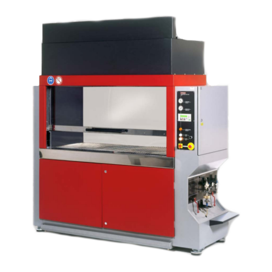
Page 25: Parts Of The Ctu
Parts of the CTU Parts of the CTU Item Designation Clean room Front pane Operating panel / control cabinet Operating console Pane fixture Filter hood Visual fluid level indicator Rinsing fluid micronic filter [22] Return filter [33] Rinsing fluid reservoirs CTU 2xxx series Page 25 / 108 en-US... -
Page 26: Control Elements On The Operating Panel
Parts of the CTU Control elements on the operating panel Item Designation Return-line vacuum indicator Rinsing medium pressure indicator Text display TD200 Reservoir change-over active indicator "Operation" signal lamp "Stand-by" signal lamp Operating mode selector switch Main switch EMERGENCY STOP button CTU 2xxx series Page 26 / 108 en-US... -
Page 27: Control Elements On The Operating Console
Parts of the CTU Control elements on the operating console Item Designation Return-line rinsing fluid shut-off ball valve Return-line vacuum setting Rinsing fluid pressure setting Vacuum shut-off ball valve Threefold filter membrane holder Compressed air shut-off ball valve Compressed air supply CTU 2xxx series Page 27 / 108 en-US... -
Page 28: Preparing The Ctu For Operation
Preparing the CTU for operation Preparing the CTU for operation Setting up the CTU Make sure that the CTU is on a level, horizontal surface. Make sure that the CTU is at least 5 cm from the wall or devices located at the back, that there is enough space (≥... -
Page 29: Setting Up The Electrical Connection Of The Ctu
Preparing the CTU for operation Setting up the electrical connection of the CTU The CTU is supplied with a power plug fitted. DANGER Dangerous electrical voltage warning Danger of fatal injury ► Any work involving the power supply may only be done by a properly trained, certified electrician. -
Page 30: Connecting The Compressed Air
Preparing the CTU for operation Connecting the compressed air The inlet for the compressed air supply is located at the right on the operating console. The inlet is a standard connector nipple of the DN 7.2 low-pressure series. The compressed air required must be dry, de-oiled and pre-cleaned to 5 µm. Additional conditions can be found in chapter "Technical Data"... -
Page 31: Connecting An Air Extractor
Preparing the CTU for operation Connecting an air extractor The connection for discharging suctioned air to the outside or to a filter is located in the rear head section of the CTU. Screw the connecting piece [3] for a Ø 125 mm hose onto the top or rear port. Seal off the unused port with the blanking cover [1]. -
Page 32: Opening/Closing The Door
Opening/closing the door Opening/closing the door The door design varies depending on the model: Door with several access holes Door with gloves Door with several access holes and small pane The door should only ever be moved using the handle provided. CTU 2xxx series Page 32 / 108 en-US... -
Page 33: Door With Several Access Holes
Opening/closing the door Door with several access holes CAUTION Falling parts Risk of injury to the feet ► Wear safety shoes The access holes in the door are sealed off with the covers provided. These are placed on the pane and remain there thanks to the integrated magnets. Ensure that the covers are properly fixed in place. -
Page 34: Door With Gloves
Opening/closing the door Door with gloves The gloves are permanently attached and must be checked for damage at regular intervals. See chapter "Checking the gloves" on page 83 for more information. CTU 2xxx series Page 34 / 108 en-US BeWa CTU2000 3160738h en-us 2018-11-15.docx 2018-11-15... -
Page 35: Installing Gloves
Opening/closing the door Installing gloves Prepare the gloves before installation. To do so, roll up the gloves from the back for about 5 cm to form a roll, like in the following illustration. Make sure that the text / labelling on the inside of the glove is on the side into which you put your hand. -
Page 36: Door With Several Access Holes And Small Pane
Opening/closing the door Door with several access holes and small pane CAUTION Falling parts Risk of injury to the feet ► Wear safety shoes The access holes in the door are sealed off with the covers provided. These are placed on the pane and remain there thanks to the integrated magnets. Ensure that the covers are properly fixed in place. -
Page 37: Operating The Filter Membrane Holder
Operating the filter membrane holder Operating the filter membrane holder When the CTU is delivered, you get the following two options to use the filter membrane holder. Only close the ball valve (3) to prevent fluid from escaping. Filter membrane holder CTMH (ContaminationTest Membrane Holder) The design presses the filter membrane in the lower part (2) of the filter membrane holder function-tight to the upper part. -
Page 38: Cascading Filter Membrane Holder Ctmh
Operating the filter membrane holder Cascading filter membrane holder CTMH Cascade filter membranes as shown in the following illustration: Item Designation Coupling Hose connection Diffuser (A diffuser ensures that the analysis fluid is evenly distributed over the entire filter membrane) Upper part of the filter membrane holder Filter membrane, 100 µm... -
Page 39: Filter Membrane Holder With Union Nut
Operating the filter membrane holder Filter membrane holder with union nut The fine thread on the union nut (1) means that the lower part (2) of the filter membrane holder is pressed against the upper part preventing leakage and ensuring that the membrane works properly. To close the filter membrane holder, lift the lower part (2) up to the upper part and tighten the union nut (1) clockwise. -
Page 40: Filter Membrane Holder With Clamp
Operating the filter membrane holder Filter membrane holder with clamp NOTICE Operation without an intermediate ring / supporting sieve Leak in the filter membrane holder ► The membrane holder only seals effectively when: - a vacuum is applied - a supporting sieve is inserted with a filter membrane ►... -
Page 41: Cascading Filter Membranes
Operating the filter membrane holder Cascading filter membranes Cascade filter membranes as shown in the following illustration: Item Designation Coupling Hose connection Diffuser (A diffuser ensures that the analysis fluid is evenly distributed over the entire filter membrane) Upper part of the filter membrane holder Filter membrane 100 µm Filter membrane 20 µm... -
Page 42: Changing The Filter Membrane
Changing the filter membrane Changing the filter membrane The ball valve on the filter membrane holder serves as an isolation valve for ultrasonic operation or for emergencies. Ensure that the analysis fluid has been completely sucked away before you remove the filter membrane. Hold the holder with one hand on the lower part. - Page 43 Changing the filter membrane Fit a new filter membrane on the supporting sieve. Pick up the union nut. Position the lower part together with the filter membrane underneath the upper part. Screw on the union nut clockwise. NOTICE Do not use any tools. CTU 2xxx series Page 43 / 108 en-US...
-
Page 44: Labeling The Filter Membrane
Changing the filter membrane Labeling the filter membrane Label the filter membrane that you just removed using a clear & logical system. An example of labeling filter membranes: xyz-1-A-005 Current sample series, component designation Number of membranes created for a measurement series If several equivalent rinsing operations are to be performed for a component, A, B, C and Z are used for creating a random sample. -
Page 45: Operating The Text Display Td 200
Operating the text display TD 200 Operating the text display TD 200 Apart from setting the pressure and selecting the operating mode, you can control all functions using the text display. The functions in the top half of the buttons can be selected directly by pressing these buttons. - Page 46 Operating the text display TD 200 Inscriptio Buttons Function ENTER Confirming entries and selections Cancelling entries or selections -> OPERATING MENU (password- protected) -> DIAGNOSTICS MENU (password- protected) SHIFT Switching the button assignment + / - Selection buttons used to select individual functions STOP Canceling all functions...
-
Page 47: Ctu Switching On
CTU switching on Turn the operating mode selector switch to "Stand-by" and switch the CTU on at the main switch. The text display will output the HYDAC FILTER SYSTEMS following message… Contamination Test …after approx. 10 seconds, this Contamination Test message will appear…... -
Page 48: Selecting The Operating Mode
Operating the text display TD 200 Selecting the operating mode The operating mode is set using the selector switch at the front. Stand-by When you switch the unit to stand-by: • The compressed air line is blocked off. • The reservoirs are adjusted to normal pressure and then sealed off. •... -
Page 49: Setting The Vacuum For Suctioning Off The Rinsing Fluid
Operating the text display TD 200 Setting the vacuum for suctioning off the rinsing fluid To set this, proceed as follows: Switch the shut-off ball valve of the compressed air supply to "on". To turn on the vacuum generator, press the button on the text display. -
Page 50: Filling/Refilling Rinsing Fluid
The reservoirs are overfilled. ► Add only the required indicated fill quantity for the test fluid. ► If the unit is overfilled, contact the HYDAC Service Department. Fill quantity during initial filling 20 liters CTU 2xxx series Page 50 / 108 en-US BeWa CTU2000 3160738h en-us 2018-11-15.docx... - Page 51 Operating the text display TD 200 Check the fill levels of reservoirs B1 / B2 using the visual fluid level indicator. Avoid overfilling the reservoirs. Close the "RINSING FLUID return line" shut-off valve. Remove the filter membrane from the filter membrane holder. Message on text display.
- Page 52 Operating the text display TD 200 Open the "RINSING FLUID return line" shut-off valve. The lamp for the reservoir change-over lights up briefly. This goes out once the rinsing fluid can be suctioned. Now fill the rinsing fluid in the drain pan of the clean room.
-
Page 53: Selecting The Rinsing Volume
Operating the text display TD 200 Selecting the rinsing volume This menu allows you to predefine 10 different rinsing volumes so that you can call them up at a later point. Message on text display. Contamination Test Press OK button to start Press the buttons. -
Page 54: Performing The Contamination Test
Operating the text display TD 200 Performing the contamination test The "Contamination Test" operating mode can be used to rinse components in a defined manner. CAUTION Spraying "G60 Spezial" test fluid Health hazard ► Keep the door to the analysis chamber closed as far as possible during the spray extraction process. - Page 55 Operating the text display TD 200 buttons in increments. Confirm the selection by pressing the button. The rinsing volume predefined using "SET" is used again for the next contamination test. Contamination Test Press the button. V=xx.x L Q=y.y L/M V = remaining volume (in liters) until the contamination test is completed Q = current flow rate (in liters/minute) Rinse the test object using the...
-
Page 56: Cleansing The Clean Room Automatically
Operating the text display TD 200 Cleansing the clean room automatically CAUTION Spraying analysis fluid Danger of eye injury ► When cleaning the clean room, the door must remain firmly closed. The automatic cleaning of the inner chamber causes the clean room to be cleansed in a defined manner. -
Page 57: Automatic Reservoir Change-Over
Operating the text display TD 200 before the set cleaning time elapses. There is still analysis fluid in the Cleaning completed collecting pan after the cleaning time Press OK to continue has elapsed. Only press the button once the clean room has been completely emptied. -
Page 58: Ctu Switching Off (Power Down)
Operating the text display TD 200 CTU switching off (Power Down) To switch off the CTU, proceed as follows: The display outputs the following Contamination Test message as a default. Press OK button to start Contamination Test Press the button and then the Press OK button to start button. -
Page 59: Preparing The Ctu For Operation
Preparing the CTU for operation Preparing the CTU for operation WARNING When using "G 60 Spezial" as the test fluid Warning of flammable substances ► Open flames are prohibited near the CTU. Proceed as follows for initial commissioning: Take the supporting sieve supplied and put See page 32 for details. -
Page 60: Clean-Room Conditions In The Analysis Chamber - Rinsing Of The Inner Chamber
Preparing the CTU for operation Clean-room conditions in the analysis chamber - Rinsing of the inner chamber Before starting a series of contamination tests, cleanse the clean room of the CTU in a defined manner using the volume or time/duration in the rinsing program "Cleansing the clean room automatically". -
Page 61: Performing Maintenance
Performing maintenance Performing maintenance Perform the maintenance tasks described below. WARNING The system is pressurized Danger of bodily injury ► Depressurize the system before working on it. ► After being switched off, the system depressurizes automatically. WARNING When using the "G 60 Spezial" as the test fluid Warning of flammable substances ►... -
Page 62: Maintenance Work
Performing maintenance Maintenance work The maintenance and servicing to be performed periodically is described in the following. The CTU’s serviceability, operational reliability and life expectancy depend on performing maintenance and servicing work regularly and carefully. Check all hoses for leaks or signs of brittleness Visually inspect the electrics. -
Page 63: Inspecting/Cleaning The Machine Compartment
Performing maintenance Inspecting/cleaning the machine compartment As a result of air filters and leaks, test medium may collect at the bottom of the machine compartment in the CTU. If the machine compartment is opened, it must be well ventilated. Inspect and clean the collecting pan of the CTU on a weekly basis. -
Page 64: Changing The Filter Element - Type Lf
Performing maintenance Changing the filter element – type LF LF in-line filter Item Designation Filter element including O-ring (2) O-ring O-ring Support ring Sealing ring O-ring Repair kit, consisting of: O-ring [2], O-ring [3], support ring [4], sealing ring [5], O-ring [6] - Wrench = 27 mm CTU 2xxx series... - Page 65 Performing maintenance To change the filter, proceed as follows: Open both front doors. Determine which filter housing needs to be changed. Unscrew the filter bowl in a counterclockwise direction using the A/F 27 wrench and remove it in a downward motion.
- Page 66 Performing maintenance Slide the new filter element onto the mounting pin applying slight pressure and turning it. When installing the new filter element, check to see whether the designation on the new element corresponds to the designation on the old one.
-
Page 67: Changing The Filter Element - Type Mrf1
Performing maintenance Changing the filter element – type MRF1 - Strap wrench (for opening the union nuts) - Allen wrench = 6 mm To change the filter, proceed as follows: Open both front doors. Drain the test fluid from the filter housing. To do that, carefully unscrew the drain plug (2) at the bottom end of the filter bowl in a clockwise direction using a 6... - Page 68 Performing maintenance Clean the filter bowl and sealing surface. Clean the sealing surface on the filter head. Check the O-ring for damage. Moisten the O-ring with the operating medium. For easy installation of the filter element, wet the O-ring with the operating medium.
- Page 69 (1) Before screwing the union nut back on, apply a lubricant. We recommend using white Vaseline as a lubricant HYDAC part no. 632391 (2) Screw the filter bowl over the union nut onto the filter head in a counterclockwise direction.
-
Page 70: Removing/Fitting Halogen Lights (Ctu Up To Manufacture Year 2006)
Performing maintenance Removing/fitting halogen lights (CTU up to manufacture year 2006) The clean room is lit using three or four halogen lights. Item Designation Bulb holder with clips Bulb Clamping ring Top part of light with glass and sealing ring CTU 2xxx series Page 70 / 108 en-US... - Page 71 Performing maintenance To change the halogen bulb, proceed as follows: CAUTION Hot surface Danger of burns ► Allow the halogen lights to cool down before removing them. Switch the CTU off and allow the halogen lights to cool down. Remove the halogen lights by pulling them out of the light rail.
-
Page 72: Light Spare Parts
Performing maintenance The halogen light is now assembled. Plug the bulb socket in. 10. Push the clips of the halogen light together and slot the halogen light into the corresponding opening. 11. Switch the CTU on and check that the halogen lights work. -
Page 73: Removing/Fitting Led Lights (Ctu 2200 / 2400 From Manufacture Year 2013)
Performing maintenance Removing/fitting LED lights (CTU 2200 / 2400 from manufacture year 2013) The clean room is lit using four LED lights. These LED lights can only be replaced as a whole. CTU 2xxx series Page 73 / 108 en-US BeWa CTU2000 3160738h en-us 2018-11-15.docx 2018-11-15... -
Page 74: Checking/Maintaining The Spray Gun
Performing maintenance Checking/maintaining the spray gun Item Designation Spray gun handle piece Filter holder (including filter) Hose with screwed fittings, length 1.8 m Spray nozzle Changing the spray nozzle The following spray nozzles are available as accessories; see the list of spare parts and accessories. -
Page 75: Replacing The Hose For The Spray Gun
Performing maintenance To change the spray nozzle, proceed as follows: Switch the CTU off via the main switch. Direct the spray nozzle into the clean room and actuate it to relieve the pressure in the spraying system. Unscrew the spray nozzle 4.0 from the filter holder 2.0 in a counterclockwise direction using a wrench. -
Page 76: Calibrating The Flow Rate Meter
Read the volume on the measuring beaker. A deviation of +/- 5% (4.75 - 5.25 liters) is within the tolerance. The flow rate meter will need to be recalibrated if the deviation is greater. Contact the HYDAC Service Department. The calibration by gauging is completed. Cleaning the analysis chamber Clean the analysis chamber every week. -
Page 77: Cleaning The Door
Performing maintenance Cleaning the door Clean the see-through door regularly. CAUTION Electrostatic charging Warning of uncontrolled electrical discharge ► Always clean the door with a moist, lint-free cloth. ► Do not use a dry cloth. Statically charged door In certain circumstances, the door can become statically charged. One possible cause of this is when two non-conducting substances, e.g., CTU gloves (neoprene), see-through door (Makrolon), cleaning cloths (cellulose or cotton), are rubbed against one another, thus causing static... -
Page 78: Changing The Clean-Room Filters
Performing maintenance Changing the clean-room filters When the CTU is switched on, there is overpressure in the clean room. This overpressure is generated by a fan module above the clean room. This fan module contains a prefilter mat and a main filter to ensure clean supply air. Replace the prefilter and main filter regularly. -
Page 79: Replacing The Main Filter
Performing maintenance Replacing the main filter When the prefilter mat is changed regularly, the main filter can be used for years without it requiring maintenance. To ensure trouble-free operation, we recommend replacing the main filter at least every two years. The main filter can be accessed and replaced via the analysis chamber. -
Page 80: Replacing The Main Filter Of A Ctu 2200 / 2400
Performing maintenance Description complete. Replacing the main filter of a CTU 2200 / 2400 Description Switch the CTU off via the main switch and allow the halogen lights to cool down. Undo the 10 screws at the bottom of the filter. -
Page 81: Emptying The Intermediate Pan
Performing maintenance Emptying the intermediate pan When suctioning the air out of the analysis chamber, rinsing fluid may get suctioned along with this during a contamination test. This is collected in an intermediate pan under the analysis chamber. Empty this intermediate pan depending on the application conditions, however at least once a week. -
Page 82: Draining The Reservoirs
Performing maintenance Draining the reservoirs Select the "Contamination Test" operating mode and select a rinsing volume of approximately 20 liters. Remove the spray nozzle of the spray gun. Place a suitable container (≥ 20 liters) underneath to catch the old rinsing fluid. Contamination Test Pressing the button takes you... -
Page 83: Reservoir Filling/Refilling
Performing maintenance Reservoir filling/refilling To fill/refill the reservoirs with test fluid, follow the instructions given on page Checking the gloves The gloves are subject to wear both mechanically and chemically. Mechanical wear - cuts and tears result from components with sharp edges and wear can be accelerated by components with rough surfaces. -
Page 84: Permeation Of Protective Gloves According To En 374-3:1994
Performing maintenance Permeation of Protective Gloves According to EN 374-3:1994 This standard pertains to determining the resistance provided by the material of protective gloves against the permeation of nongaseous, potentially hazardous chemicals when subjected to continuous contact. For each chemical the combinations of protective glove and test chemical are classified according to their penetration/breakthrough time in which the glove prevents permeation. - Page 85 This information is not designed as a substitute for suitability testing conducted by the end user. Consequently, HYDAC assumes no liability or responsibility for the information provided in this list. CTU 2xxx series...
-
Page 86: Checking The Filter Regulator
Performing maintenance Checking the filter regulator The following tasks need to be carried out when setting and cleaning the filter regulator. Setting the filter regulator To set the pressure desired at the filter regulator, pull the setting knob up and turn it until the pressure is below the new pressure to be set. -
Page 87: Disassembling The Filter Regulator
Performing maintenance Disassembling the filter regulator Only disassemble the filter regulator when the pneumatic system is depressurized. Remove the filter regulator to disassemble it. Disassembling the top part Pull the setting knob [1] upwards and turn it all the way in a counterclockwise direction until it will go no further. -
Page 88: Assembling The Bottom Part
Remedying error messages/malfunctions The filter regulator is re-assembled in reverse order. First the components of the lower assembly are replaced in the housing. The upper assembly is then put back together. If new seals are used during re-assembly, thoroughly grease them prior to installation. Assembling the bottom part Insert the O-ring Ø... -
Page 89: Remedying Error Messages/Malfunctions
Remedying error messages/malfunctions Remedying error messages/malfunctions When operating the CTU, the following error messages may appear on the display: Error message Reason Rectification EMERGENCY STOP The EMERGENCY Unlock the STOP button was EMERGENCY STOP pressed. button. Fresh air valve MPS The motor protection Switch the motor switch of the clean air fan... - Page 90 Remedying error messages/malfunctions Error message Reason Rectification Fuse triggering F1- There is excess current Switch the fuse on again. in the electrical circuit Check the electricity concerned (see the consumption and look for electrical circuit diagram). the cause of the error. Please top up rinsing Reservoirs B1 and B2 Top up the rinsing fluid...
-
Page 91: Hydraulic Circuit
Hydraulic circuit Hydraulic circuit CTU 2xxx series Page 91 / 108 en-US BeWa CTU2000 3160738h en-us 2018-11-15.docx 2018-11-15... - Page 92 Hydraulic circuit Item Designation Compressed air supply ball valve Output check valve B1 Return check valve B1 Output check valve B2 Return check valve B2 Return check valve Filter membrane holder ball valve Return ball valve Pan draining ball valve Spray gun Ball valve of ring main Pressure control valve (vacuum)
- Page 93 Hydraulic circuit Item Designation B2 bleeding solenoid valve Silencer Silencer Silencer Silencer Silencer Pressure gauge (vacuum setting) Pressure gauge (vacuum setting) Pressure gauge (vacuum setting) Pressure gauge (vacuum setting) Compressed air filter Compressed air filter Filter membrane holder Level switch B1 Level switch B2 Clean room Compressed air supply...
-
Page 94: Locating Spare Parts
Locating spare parts Locating spare parts Use only original spare parts and accessories. When ordering spare parts, always specify the designation of the unit (type, material no., serial no., year of manufacture). Designation p/no. Qty. Qty. Qty. Built-in light for analysis chamber lighting 6028918 (without bulb and socket) Socket for built-in light... - Page 95 Locating spare parts Designation p/no. Qty. Qty. Qty. Spare parts set for spray gun including jet 6027105 nozzle, fan nozzle, funnel nozzle (stainless steel) Valve seal for spray gun 6042374 Filter regulator (without pressure gauge) 6004671 Pressure gauge for filter regulator 6006377 Filter insert 30 µm for filter regulator 6039258...
-
Page 96: Disposing Of The Ctu
Disposing of the CTU Designation p/no. Qty. Qty. Qty. Vacuum generator 6024223 Float switches for reservoirs B1 and B2 6022887 Supporting sieve for membrane holder Ø 47 6024224 Filter membrane 5 µm, Ø 47 mm 6020761 Color: white, surface: smooth, 1 pckg contains 100 Analysis fluid G60 (30-liter container) 3205511... -
Page 97: Technical Data
Technical Data Technical Data Dimensions Height 2500 mm CTU 2000 Width 1470 mm Depth 900 mm Dimensions Height 2500 mm CTU 2200 Width 2170 mm Depth 900 mm Dimensions Height 3600 mm CTU 2400 Width 2270 mm Depth 1595 mm ≈... - Page 98 Technical Data Suction speed of the 1.14 l/min at 0.7 bar vacuum analysis fluid Collecting pan volume CTU 2000 = 30 liters CTU 2200 / CTU 2400 > 30 liters Emission sound < 70 db(A) pressure level LPA CTU 2xxx series Page 98 / 108 en-US BeWa CTU2000 3160738h en-us 2018-11-15.docx...
-
Page 99: Attachment
Fax: +49 6897 509 9046 E-mail: filtersystems@hydac.com For repair work or complaints, please contact our central customer service department: HYDAC SYSTEMS & SERVICE GMBH Friedrichsthaler Straße 15, Werk 13 66540 Neunkirchen-Heinitz Phone: +49 6897 509 883 Fax: +49 6897 509 324 E-mail: service@hydac.com... -
Page 100: Model Code
Attachment Model Code 0 - M - Z - Z Product CTU = Contamination Test Unit Series = 2000 Series Size (height x width x depth) = Clean-room dimensions 670 x 900 x 600 mm = Clean-room dimensions 670 x 1600 x 600 mm = Clean-room dimensions 1400 x 1700 x 1400 mm Analysis... -
Page 101: Explanation Of Terms And Abbreviations
Attachment Explanation of terms and abbreviations An explanation of terms and abbreviations follows below: °C Degrees Celsius abs. Absolute (e.g. in pressure specifications) Alternating current Air Bleed Ventilation / air bleed port Analysis fluid Test fluid loaded with particles up to the filter membrane after spray extraction. - Page 102 Attachment Inlet INLET Inlet Meter Maximum mbar Millibar (1 mbar = 0.001 bar) Minimum Millimeter Nitrile rubber Newton meters (torque specification) Switched off Switched on Outlet OUTLET Outlet Test fluid Fluid for general operation. (Rinsing fluid / analysis fluid). Sec. Second(s) Rinsing fluid Test fluid for spray extraction.
-
Page 103: Index
Attachment Index Flash point 101 Float switch 96 Flow rate 95 Accessories 20 accident prevention 13, 17 Air vent 20, 31 ambient temperature 97 Hazard symbol 10 Analysis 96, 100, 101 Hose connection 38, 41 Auxiliary personnel 16 Imprint 2 bleeding 92, 93 IN 102 In case of emergency 17... - Page 104 Attachment switching off 58 switching on 47, 54 Remedy 77 replacement 72, 75, 79, 81 Transport 16 Troubleshooting 16 Type label 19 select 8, 45, 46, 53, 82 Service 50, 76, 99 setting 27, 45, 52, 86, 87, 93 Signal word 9, 10 signal words 9, 10 Vacuum 27, 96 Size 100...
- Page 108 HYDAC FILTER SYSTEMS GMBH Industriegebiet Postfach 1251 66280 Sulzbach/Saar 66273 Sulzbach/Saar Germany Germany Tel: +49 (0) 6897 509 01 Central Fax: +49 (0) 6897 509 9046 Technical Department Fax: +49 (0) 6897 509 577 Sales Internet: www.hydac.com E-mail: filtersystems@hydac.com...
Need help?
Do you have a question about the CTU 2 Series and is the answer not in the manual?
Questions and answers