Advertisement
U-UDS5000WC Drawing Table Assembly Instructions
[1] - M4x12mm Screws
(18 each)
[5] - Knobs - Male
(4 each)
[9] - Hinge
(4 each)
[A] - Table Top (1 each)
[E] - Tilt Bracket End
(2 each)
If you have difficulty assembling your U-DS5000WC Table
Martin Universal Design, Inc. Customer Service Hot Line at
it is not necessary to contact your dealer, our Customer Service Rep. will forward them
Additional Tools needed: Phiillips Screwdriver
Hardware List
[2] - Nuts
(2 each)
[6] - Washer with small
hole (4 each)
[11] - Wrench
(1 each)
Parts List
[B] - Base foot (2 each)
[F] - Tilt Bracket (2 each)
IMPORTANT
or need customer service assistance.
Please call:
1-313-895-0700.
If you need additional parts,
to you immediately.
4444 Lawton Avenue, Detroit, MI 48208 USA • Tel:(313)895-0700/Fax:(313)895-0709
Email: Custservmud@aol.com • visit us at www.MartinUniversalDesign.com
[3] - M6x8mm Allen
Screw (4 each)
[7] - Washer with large
hole (4 each)
[12] - Allen-Wrench
(1 each)
[C] - Foot Rest Cross
Support (1 each)
[G] - Pencil Edge
(1 each)
[4] - M6x12mm Allen
Screw (2 each)
[8] - Threaded Rubber
Feet (4 each)
[D] - H-Frame
Support
(1 each)
Pg. 1
Advertisement
Table of Contents

Related Manuals for Weber U-UDS5000WC


Summary of Contents for Weber U-UDS5000WC
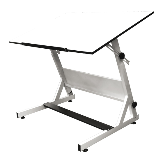
- Page 1 U-UDS5000WC Drawing Table Assembly Instructions Additional Tools needed: Phiillips Screwdriver Hardware List [1] - M4x12mm Screws [2] - Nuts [3] - M6x8mm Allen [4] - M6x12mm Allen (18 each) (2 each) Screw (4 each) Screw (2 each) [5] - Knobs - Male...
- Page 2 U-UDS5000WC Drawing Table Assembly Instructions IMPORTANT: ASSEMBLY IS EASIER AND SAFER WITH TWO PEOPLE STEP 1] Assembly Base of Table Begin by taking the [2] Lower Base Feet (part B) and attach the foot rest (part C) to the Lower Base Feet using [2] M4 x 12mm screws (part 1).
- Page 3 U-UDS5000WC Drawing Table Assembly Instructions IMPORTANT: ASSEMBLY IS EASIER AND SAFER WITH TWO PEOPLE STEP 3] Tilt Bracket Assembly Lay table top onto flat carpeted or cardboard sur- face with holes facing up (to protect from scratching table top). Attach the Tilt Bracket End (part E) to the table top in the position as shown in FIG 3 using [2] each M6 x 8mm Allen Screws (part 3) per bracket.
- Page 4 U-UDS5000WC Drawing Table Assembly Instructions IMPORTANT: ASSEMBLY IS EASIER AND SAFER WITH TWO PEOPLE STEP 5] Table Adjustments To Raise or Lower the height of the table, loosen the Lower knobs found on the channeled Base supports. Raise or Lower the table to your desired position and re-tighten the knobs to secure.
Need help?
Do you have a question about the U-UDS5000WC and is the answer not in the manual?
Questions and answers