Advertisement
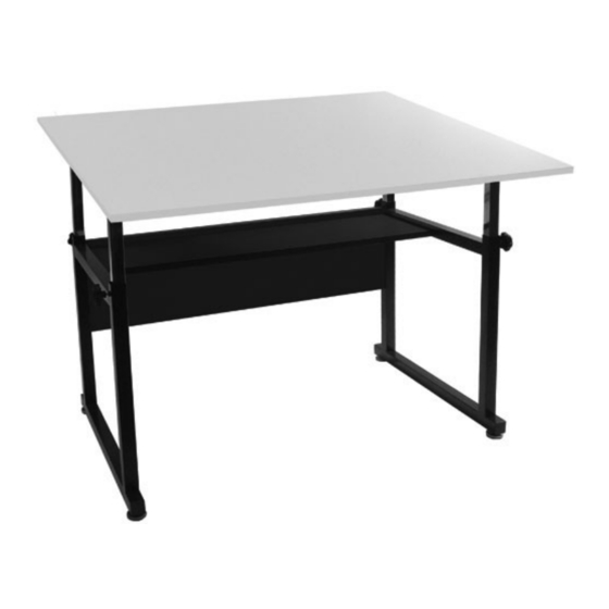
Ridgeline
Assembly Instructions
U-DS6000P
IMPORTANT
If you have difficulty assembling your U-DS6000P Ridgeline Table
or need customer service assistance. Please call:
Martin Universal Design, Inc. Customer Service Hot Line at 1-313-895-0700.
If you need additional parts, it is not necessary to contact your dealer,
our Customer Service Rep. will forward them to you immediately.
Martin Universal Design, Inc. • Detroit, MI 48208 USA
Tel: 313-895-0700 • E-mail: custservMUD@aol.com
www.MartinUniversalDesign.com
Since 1853
November 09, RPI
Advertisement
Table of Contents

Subscribe to Our Youtube Channel
Related Manuals for Weber Ridgeline U-DS6000P


Summary of Contents for Weber Ridgeline U-DS6000P
- Page 1 Ridgeline Assembly Instructions U-DS6000P IMPORTANT If you have difficulty assembling your U-DS6000P Ridgeline Table or need customer service assistance. Please call: Martin Universal Design, Inc. Customer Service Hot Line at 1-313-895-0700. If you need additional parts, it is not necessary to contact your dealer, our Customer Service Rep.
- Page 2 Ridgeline Since 1853 Hardware Parts List 2PCS 4PCS 2PCS 2PCS Height Adj. Tube w/ hole Side Support Floor Leveler Panel 2PCS 2PCS Height Adj. Tube 4x14mm Screw Tilt Mechanism 4PCS 12PCS 2PCS 4PCS 6x12mm Bolt Small Washer Large Washer Knob 2PCS 2PCS 2PCS...
- Page 3 Ridgeline Assembly Since 1853 NOTE: FIG 1 We reccommend the The Assembly of this table to be performed with two adult people. STEP 1 Begin assembly of the Ridgeline table by taking the side support (part A) and attaching the oor levelers (part B) to the side supports.
- Page 4 Ridgeline Assembly Since 1853 FIG 4 STEP 4 Attaching Height Adjustment Tubes. To attach the height adjustment tubes (part D + part F), use 4 each (part I) knob. Leave a 12” gap from the top of the side supports, and secure the tubes in place by tightening the tubes with the knobs.
- Page 5 Ridgeline Assembly Since 1853 FIG 6 STEP 6 Attach Base to Top Attaching Tilt Mechanism to Height Adjustment Tube. To attach the tilt mechanism (part G) to the height adjustment tube, you will need the following parts 1 each (part M) 8x50mm bolt, 2 each (part L) washer, 1 each (part K) washer, 1 each (part N) nut.
Need help?
Do you have a question about the Ridgeline U-DS6000P and is the answer not in the manual?
Questions and answers