Table of Contents
Advertisement
Quick Links
Advertisement
Table of Contents

Subscribe to Our Youtube Channel
Related Manuals for Enerpac PID Series


Summary of Contents for Enerpac PID Series
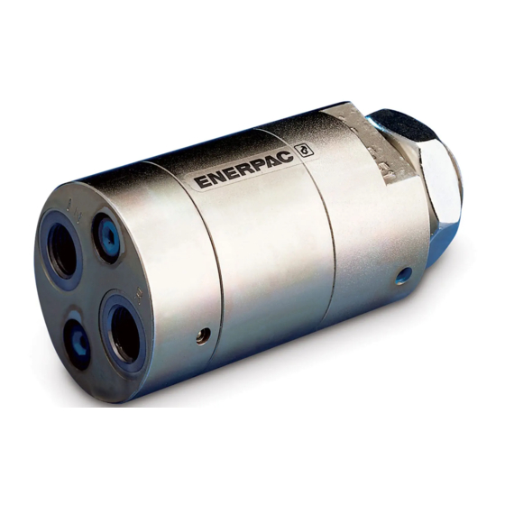
- Page 1 Operation and Maintenance Manual Hydraulic Oil-to-Oil Intensifiers Series Document Number: L4523 Document Revision: A Issue Date: October, 2021 Language: English PIDxxxA PIDMxxx PIDVxxxA PIDHxxx PIDVHxxx To reduce the risk of injury, user must read and understand this document before use.
- Page 2 ABOUT US Enerpac is a global market leader in high pressure hydraulic tools, controlled force products, portable machining, on- site services and solutions for precise positioning of heavy www.facebook.com/enerpac loads. As a leading innovator with over a 100 year legacy, Enerpac has helped move and maintain some of the largest www.youtube.com/enerpac...
-
Page 3: Table Of Contents
CONTENTS PAGE SAFETY ..............................4 SPECIFICATIONS AND PRODUCT DATA ....................6 DESCRIPTION ............................12 PRINCIPLES OF OPERATION ........................ 12 INSTALLATION AND SETUP........................12 OPERATION ............................. 15 SERVICE ..............................18 TROUBLESHOOTING ..........................18 REPLACEMENT PARTS .......................... 20 L4523_a... -
Page 4: Safety
• Be sure that all personnel involved with operating damage to the product and/or damage to other property. or servicing the workholding devices read and Enerpac cannot be responsible for any damage or injury understand the information contained in the from unsafe use, lack of maintenance, or incorrect manuals included with these devices. - Page 5 • Some PID Series intensifier models are capable of providing a maximum pressure above 5000 psi [350 bar]. Operation at pressures above 5000 psi [350 bar] requires the use of high pressure fittings. Contact Enerpac for additional details. • Read, understand and follow all communicated safety precautions and related information included on the following pages of this manual.
-
Page 6: Specifications And Product Data
Face Manifold 5000 5.0:1 290-1000 3.85 - - - - - - PIDM662 Face Manifold 5000 6.6:1 290-758 3.85 - - - - - - Operating pressures above 5000 psi [350 bar] require high pressure fittings. Contact Enerpac for details. L4523_a... - Page 7 PIDM502 Face Manifold 5.0:1 20-70 1.75 - - - - - - PIDM662 Face Manifold 6.6:1 20-53 1.75 - - - - - - Operating pressures above 350 bar [5000 psi] require high pressure fittings. Contact Enerpac for details. L4523_a...
- Page 8 2.3 External Dimensions & Port Locations - PIDxxxA Models Return Port Outlet Port Inlet Port Dimension or Port Size Dimension or Port Size Item Item inch inch ø 1.17-1.18 ø 29.8-30.0 4.32-4.34 109.8-110.2 M24 x 1.5 1.61 40.9 0.74-0.76 18.8-19.2 1.09-1.10 27.8-28.0 Outlet Port...
- Page 9 2.5 External Dimensions & Port Locations - PIDVxxxA Models D03/CETOP 3 VALVE MOUNTING Dimension Dimension Item Item inch inch ø 1.97 ø 50.0 2.36 60.0 6.64 168.7 0.34 2.72 69.0 0.41 10.5 1.97 50.0 Ports: A (advance), B (retract), P (pump) and T (reservoir) L4523_a...
- Page 10 2.6 External Dimensions & Port Locations - PIDVHxxx Models D03/CETOP 3 VALVE MOUNTING Dimension Dimension Item Item inch inch ø 2.76 ø 70.0 2.83 72.0 8.53 216.7 0.74 18.8 3.15 80.0 0.41 10.5 2.76 70.0 Ports: A (advance), B (retract), P (pump) and T (reservoir) L4523_a...
- Page 11 2.7 External Dimensions & Port Locations - PIDMxxx Models FACE MOUNTING Dimension Dimension Item Item inch inch ø 1.97 ø 50.0 0.73 18.5 4.79 121.7 1.97 50.0 0.87 22.0 1.22 31.0 2.72 69.0 0.28 ø 0.24 ø 6.2 2.17 55.0 0.37 Maximum ø...
-
Page 12: Description
• When the maximum pressure is reached, the oscillation frequency lowers and balances at the • All current production PID Series intensifier models maximum pressure. At this point, the intensifier’s include a built-in filter screen at each port to block oscillating pump stops oscillating or oscillates very large particles such as metal chips. - Page 13 5000 psi [350 bar]. However, a sufficient inlet flow rate of approximately Contact Enerpac for additional information. 79 in³/min [1.3 lpm] is required to maintain this • Minimum hydraulic pressure at the inlet port for all capability.
- Page 14 5.7 Directional Control Valve Recommendations • To prevent hydraulic oil leakage from occurring, it is strongly recommended that an open center control valve be used with the intensifier. See re 4, upper view. Figu • Use of a closed center control valve is not recommended. See re 4, lower view.
-
Page 15: Operation
6.0 OPERATION 6.1 PIDxxxA and PIDHxxx Models When hydraulic oil enters the inlet (IN) port, it freely flows through the check valves (KV1, KV2) to the cylinder. The cylinder then advances. When cylinder pressure reaches the supply pressure, the intensifier oscillating pump (OP) automatically starts oscillating and begins to increase the pressure in the cylinder by the designated intensification factor (varies by intensifier model). - Page 16 6.2 PIDVxxxA and PIDVHxxx Models The PIDVxxxA and PIDVHxxx models function in the same manner as the PIDxxxA models (refer to Section 6.1). However, for the PIDVxxxA, the intensifier is integrated into a D03 (CETOP 3) ported manifold block. A control valve is required and must be mounted above the intensifier in a valve stack on a D03 (CETOP 3) valve manifold.
- Page 17 6.3 PIDMxxx Models The PIDMxxx models function in the same manner as the PIDxxxA models (refer to Section 6.1). However for the PIDMxxx, the intensifier is integrated into a flange mount manifold block that is designed to face-mount to a custom manifold block.
-
Page 18: Service
7.0 SERVICE Except for a few maintenance oriented items, the PID Series intensifiers contain no user-replaceable parts. Maintaining the proper filtration and flow rate of the inlet oil will help provide trouble-free operation. Service kits containing replacement filters, O-rings and orifices are available from your Enerpac distributor or authorized service center. - Page 19 8. Outlet port pressure Pressure peaks at the inlet port. Check hydraulic system for pressure fluctuates. fluctuations. If corrective actions fail to restore proper operation, take the intensifier to an Enerpac authorized service NOTICE center for diagnosis. Intensifier is not user-repairable. L4523_a...
-
Page 20: Replacement Parts
9.0 REPLACEMENT PARTS Replacement parts are shown in the following parts lists (sections 9.1 through 9.5). Refer to the parts list for your intensifier model. 9.1 Parts List for PIDxxxA Models Item 2: Apply anti-seize compound to threads. Torque to 3.7 lb-ft [5 Nm]. - Page 21 9.3 Parts List for PIDVxxxA Models (Sectional View) Item Description O-Ring Filter Screen (all ports) Items included in Parts Kit, PIDVK1. Note: Replacement inlet orifice is not available for PIDVxxxA intensifier models. L4523_a...
- Page 22 9.4 Parts List for PIDVHxxx Models (Sectional View) Item Description O-Ring Filter Screen (all ports) Items included in Parts Kit, PIDVHK1. Note: Replacement inlet orifice is not available for PIDVHxxx intensifier models. L4523_a...
- Page 23 9.5 Parts List for PIDMxxx Models 2, 3 4, 5 2, 3 Item Description Orifice, 1.6 mm, Inlet (IN) Port Filter Screen, Inlet (IN) and Return (R) Ports O-Ring, Inlet (IN) and Return (R) Ports Filter Screen, Outlet (H) Port ...
- Page 24 Enerpac Tool Group Corp N86 W12500 Westbrook Crossing Menomonee Falls, WI 53051 USA www.enerpac.com © 2021 Enerpac Tool Group, All Rights Reserved.
Need help?
Do you have a question about the PID Series and is the answer not in the manual?
Questions and answers