
Related Manuals for Flexicon FF30


Summary of Contents for Flexicon FF30
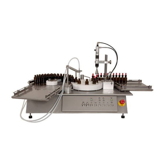
- Page 1 INSTRUCTION HANDBOOK FF30 FF30 (Example; exact model may vary) This instruction handbook is for the daily users of the equipment. FF30 IH EN 74-216-201 v1.50 Page 1 of 29...
-
Page 2: Table Of Contents
Production START and STOP ................... 21 4.6.1 Manual placing of caps ..................... 21 4.6.2 Removing bottles from collection tray ................21 Stepping bottles through the FF30 ..................21 Malfunctioning ........................22 Start-up alarms ......................... 22 Runtime alarms ......................... 22 Runtime warnings ......................24 Trouble shooting ....................... - Page 3 7.1.3 Star wheel and bottle ejector .................... 27 Service ..........................28 7.2.1 Safety coupling ......................... 28 Methods and frequency of inspections for safety functions ..........28 Change of voltage ......................29 FF30 IH EN 74-216-201 v1.50 Page 3 of 29...
-
Page 4: Introduction
Filling is performed automatically, and capping is semi-automatic. After capping the bottle is pushed to the outlet tray by a bottle ejector. FF30 is delivered without the external filler; in order to perform the filling, a filler must be connected. (See further information in section 2.4) 1.2 Abbreviations in this manual... -
Page 5: Caution And Employee Safety
INSTRUCTION HANDBOOK FF30 1.4 Caution and employee safety This manual should be read before using the FF30. It is strongly advised that Any kind of maintenance or cleaning of the machine not is carried out while power is connected. Unauthorised / non-trained personnel should not open the cover of the electrical parts. -
Page 6: General Information
Before unpacking the FF30 it should be checked if the crate is damaged. When unpacking remove all four sides of the wooden crate. Lift the FF30 away from the pallet by lifting it underneath the machine. Do not lift the machine by lifting it in the top plate. - Page 7 Bottle guide exit accessory can be mounted / hanged on the outlet tray to narrow down the passage for the bottles. Bottle guide mounted / hanged on the outlet tray guide. FF30 IH EN 74-216-201 v1.50 Page 7 of 29...
-
Page 8: Technical Specifications
INSTRUCTION HANDBOOK FF30 2.4 Technical specifications 2.4.1 Dimensions Length: 1230 mm Width: 795 mm Height: max. 730 mm (incl. Feet) Dimensions: mm / inches FF30 IH EN 74-216-201 v1.50 Page 8 of 29... -
Page 9: Buttons / Control Panel
Lights when Cap sensor sees cap during adjustment. Inlet sensor Button for Inlet sensor. Lights when Inlet sensor sees bottle during adjustment. Ready Ready button which lights when FF30 is ready Alarm / Reset Push button for cancelling errors. The button flashes if an error occurs. Fill Enables filling;... -
Page 10: Services
*note – the trays are not rectangular. See picture on the front page. 2.4.5 Ingress protection Ingress protection IP52 2.4.6 Weight Weight: app. 60 kg 2.4.7 Materials of construction ➢ AISI304 stainless steel ➢ Anodised aluminium ➢ Polyacetal FF30 IH EN 74-216-201 v1.50 Page 10 of 29... -
Page 11: Fillers
3.1 Connections FF30 must be placed on a stable and horizontal bedplate. FF30 and filler must only be connected to the specified power supply stated on the tag next to the power connections, as seen on the pictures below (red circles). -
Page 12: Mounting Of Format Parts
Finally move the guides one by one… Move the star wheel When the last guide has been removed another size of format parts can be mounted. This is done the opposite way of the dismounting procedure. FF30 IH EN 74-216-201 v1.50 Page 12 of 29... - Page 13 (red circles). Fasten the screw again. The sensor head can be adjusted forwards and backwards by moving the sensor head in the wanted direction (blue arrow and red circles). FF30 IH EN 74-216-201 v1.50 Page 13 of 29...
-
Page 14: Screw Cap Format Parts
When mounting another size of capping head, it is not necessary to touch the quick coupling. Just press the head into the coupling until it clicks. FF30 IH EN 74-216-201 v1.50 Page 14 of 29... - Page 15 Press the rim inwards to lock it. Perform some test runs and control if the capping is okay; if not – perform a new adjustment. Factory settings; see the Format Table. FF30 IH EN 74-216-201 v1.50 Page 15 of 29...
-
Page 16: Daily Use
Adjust the inlet guide by loosening the finger screws and move it to the right or left, depending on the bottle size. The bottles should be led to the first position of the star wheel; never to the outside of the star wheel. Correct adjustment Wrong adjustment FF30 IH EN 74-216-201 v1.50 Page 16 of 29... -
Page 17: Installing Inner Bottle Guide Flexible Tip
The flexible tip (6) and its mounting screws (7) should be located in the “Accessories bag 66-060-130” which came with the FF30. Assemble as pictured below and fasten the screws (7). For adjustment of the Inner Bottle Guide Movable Part see: 4.1.1 - Adjusting the round table inner bottle guide. -
Page 18: Adjustment Of The Filling Stand
The cap must be placed detachable on the top of the bottle – not screwed. Loosen the finger screw of the sensor and adjust until the light is just below the top of the cap and close to the side edge of the cap. FF30 IH EN 74-216-201 v1.50 Page 18 of 29... -
Page 19: Adjusting The Height Of Capping Head
Turn the capping head until the Insert a screwdriver and sleeve down. adjustment lock plate is visible adjust torque by turning. through the slot. Increase = clockwise Decrease = counter clockwise FF30 IH EN 74-216-201 v1.50 Page 19 of 29... -
Page 20: Adjustments
➢ Turn DELAY back to 0 ➢ Press ADJUST again to return to normal mode The value is saved when the machine is turned off. 4.5.4 Round table speed adjustment See section 2.4.2 FF30 IH EN 74-216-201 v1.50 Page 20 of 29... -
Page 21: Production Start And Stop
The cap sensor is only active when the CAP button has been activated. If a bottle enters in front of the sensor without a cap the FF30 will stop. Place the cap manually and press CAP to continue production; or press STEP to end automatic production – the star wheel will now move one position forward. -
Page 22: Malfunctioning
FF30 5 Malfunctioning The FF30 is equipped with control functions, which will stop the machine in the event of malfunctioning. If a function error is detected, the yellow ALARM/RESET (A/R) button will begin to flash and the FF30 will stop. - Page 23 Fault inside machine the round table toothed START and wheel is not turning; fault must be investigated Round table fault FILL buttons are inside machine: Check toothed belt, fuses and flashing motor. FF30 IH EN 74-216-201 v1.50 Page 23 of 29...
-
Page 24: Runtime Warnings
- The toothed belt needs tension - Check fuses External filler does not start when a bottle is - Missing or loose cable from FF30 to filler - The filler is not in “dispense mode” present under nozzle Capping station runs even if cap is missing... -
Page 25: Cleaning
➢ Remove the filling nozzle and the filling tubes 6.3 Cleaning Guidance Correct cleaning of the FF30 is carried out by washing it off with water or detergents, using a lint-free firmly wrung cloth or lint-free paper towel; subsequently the machine is wiped off with a dry cloth. -
Page 26: Maintenance & Service
7.1.1 Tension of toothed belt Both the round table and the star wheel are driven by a toothed belt. Normally these will not need tension, but should be checked yearly. FF30 IH EN 74-216-201 v1.50 Page 26 of 29... -
Page 27: Capping Unit
Note: it is the thin curved side of the wheel which is lubricated not the front or back. The contact faces between the cam of the toothed pulley and the ejector arm should be lightly lubricated with a suitable grease; e.g. ROCOL FOODLUBE EXTREME (red circles). FF30 IH EN 74-216-201 v1.50 Page 27 of 29... -
Page 28: Service
INSTRUCTION HANDBOOK FF30 7.2 Service Should service be needed, please contact W-M Flexicon or your local supplier. 7.2.1 Safety coupling The safety coupling needs to be replaced. The safety coupling is a safety component and must be replaced every 3 years. -
Page 29: Change Of Voltage
INSTRUCTION HANDBOOK FF30 8 Change of voltage The FF30 can be converted to accept another supply voltage. The conversion can be made inside the machine by moving the cables of the transformer clamps. 220/240 V AC 110/120 V AC Brown...
Need help?
Do you have a question about the FF30 and is the answer not in the manual?
Questions and answers